A visual capping system and capping method

A capping and visual technology, applied in the field of optical device processing, can solve the problem of low positioning accuracy in capping operations, and achieve high production efficiency, high precision, and high precision

Active Publication Date: 2021-10-01
GUILIN OPTOSEAL TECH CO LTD
View PDF0 Cites 0 Cited by
  • Summary
  • Abstract
  • Description
  • Claims
  • Application Information

AI Technical Summary

Problems solved by technology

[0003] In order to solve the deficiencies in the prior art, the present invention provides a visual capping system and capping method, which solves the technical problem of low positioning accuracy of the capping operation in the prior art

Method used


Image

  • A visual capping system and capping method
  • A visual capping system and capping method
  • A visual capping system and capping method

Examples


Embodiment Construction

[0041] The present invention will be further described below in conjunction with the accompanying drawings. The following examples are only used to illustrate the technical solution of the present invention more clearly, but not to limit the protection scope of the present invention.

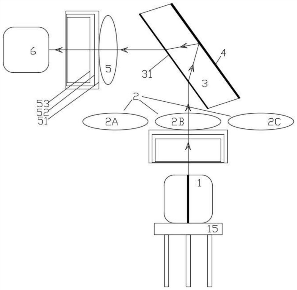
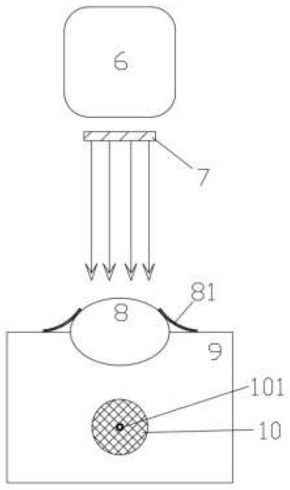
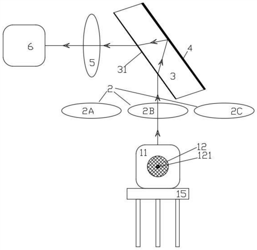
[0042] Such as Figure 1 to Figure 4 As shown: this embodiment discloses a visual capping system: including an image analysis device 6, an optical path processing component, a light source 7, a convex lens and a target object, wherein:

[0043] Target: fixed on the tube base 15, and can generate an optical path to the optical path processing component;

[0044] The optical path processing component is used to filter the optical path generated by the target object and adjust the focus.

[0045] Light source 7: fixed to the image analysis device 6, the light source 7 can also be a part of the image analysis device 6, the position coordinates of the two are fixed, and are used to emit a test ligh...


PUM


Abstract

The invention discloses a visual capping system and capping method: the system includes an image analysis device, an optical path processing component, a light source, a convex lens and an object. When sealing the cap, fix the target object on the tube base and the convex lens on the tube cap; the image analysis device obtains and records the coordinates of the target object through the optical path processing component; the light source emits a test light path to the convex lens, and adjusts the position of the light source so that the Test the optical path to form the emission lens spot; get the center point of the spot of the convex lens and mark it; according to the center point of the spot of the convex lens and the coordinates of the target, make the tube cap face the tube seat; the capping operation can be completed. The high-precision cap sealing scheme of the present invention adopts a visual recognition scheme, and has high precision, which can reach ±10um, and fully meets the needs of high-end products. The focal length of the high-precision capping solution of the present invention can be adjusted. When different chip solutions are used, the focal length can be adjusted to ensure clear identification and high precision.

Description

technical field [0001] The invention relates to the field of optical device processing, in particular to a visual capping system and a capping method. Background technique [0002] With the rapid development of the Internet, big data, artificial intelligence, and high-definition television, network bandwidth continues to increase, and high-definition video conferencing, cloud services, massive data exchange, and mobile office have become more efficient and open platforms, and terminal equipment continues to develop. Promote social intelligence and information-based office, and the requirements for network bandwidth and speed are getting higher and higher. Human beings use various methods to increase chip transmission speed. With the increase of chip speed, the requirements for optical device technology are getting higher and higher. , especially the requirements for the accuracy of the sealing cap. If the accuracy deviation will seriously affect the use of the client, it wil...

Claims


Application Information

Patent Timeline
Patent Type & Authority Patents(China)
IPC IPC(8): G02B7/04H01S5/02212G01B11/27
CPCG02B7/04H01S5/02212G01B11/27
Inventor 屈显波黄祥恩
Owner GUILIN OPTOSEAL TECH CO LTD
Why Eureka
Try Eureka