
Axial stripping and lateral wire arrangement continuous optical cable stripping device

A continuous type, stripper technology, applied in the direction of instruments, optics, light guides, etc., can solve the problems of small application range, damage, and failure to meet the use requirements, and achieve the effect of reducing fiber damage and reducing damage

Pending Publication Date: 2021-06-25
马泽睿
View PDF2 Cites 1 Cited by
  • Summary
  • Abstract
  • Description
  • Claims
  • Application Information

AI Technical Summary

Problems solved by technology

For layer-stranded optical cables, since the optical fiber is spirally wound on the supporting steel wire in the middle, the stripper can only cut the outer protective layer of the optical cable, but there is no way to remove the steel wire in the center of the optical fiber bundle.
On the other hand, traditional strippers are often only suitable for one diameter of optical cable, and there are no effective protection measures for optical fibers. current usage needs

Method used


Image

  • Axial stripping and lateral wire arrangement continuous optical cable stripping device
  • Axial stripping and lateral wire arrangement continuous optical cable stripping device
  • Axial stripping and lateral wire arrangement continuous optical cable stripping device

Examples


Embodiment Construction

[0023] The following will clearly and completely describe the technical solutions in the embodiments of the present invention with reference to the accompanying drawings in the embodiments of the present invention. Obviously, the described embodiments are only some, not all, embodiments of the present invention. Based on the embodiments of the present invention, all other embodiments obtained by persons of ordinary skill in the art without making creative efforts belong to the protection scope of the present invention.

[0024] see Figure 1-8 , the present invention provides technical solutions:

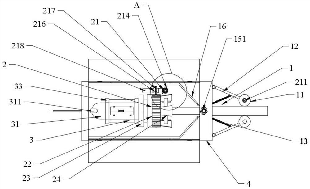
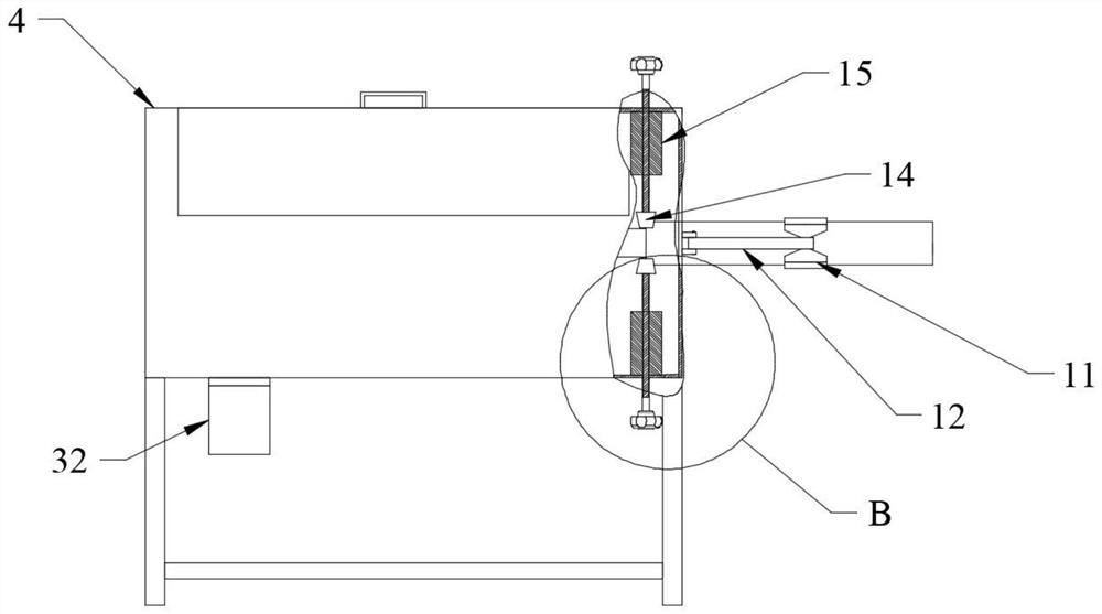
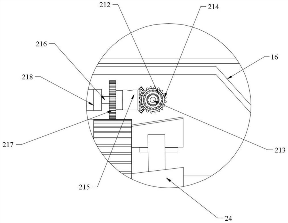
[0025] Such as figure 1 , 2 As shown, an axial stripping and lateral cable continuous type optical cable stripper includes a protective sleeve cutting assembly 1, a strengthening member removal assembly 2, an optical fiber pulling assembly 3, and a housing 4. The protective sleeve cutting assembly 1 and the housing 4 Tightly connected, the protective sleeve cutting assembly 1 is ...


PUM


Abstract

The invention discloses an axial stripping and lateral wire arrangement continuous optical cable stripping device, which comprises a protective sleeve cutting assembly, a reinforcer removing assembly, an optical fiber traction assembly and a shell, and is characterized in that the protective sleeve cutting assembly is fixedly connected with the shell, the protective sleeve cutting assembly is located at one side of the shell, the reinforcer removing assembly is located in the shell, the reinforcer removing assembly is connected with the protective sleeve cutting assembly, one part of the optical fiber traction assembly extends into the shell, one end, extending into the shell, of the optical fiber traction assembly is fixedly connected with the reinforcer removing assembly, and the partial side edge, located outside the shell, of the optical fiber traction assembly is fixedly connected with the shell. According to the invention, the layer-stranded optical cable is reversely unwound according to an original winding angle by the reinforcer removing assembly, so that a steel wire serving as a reinforcer can be separated from an optical fiber; and the inner diameter can be freely adjusted by the inner diameter adjusting component, so that optical cables with different diameters can be stripped by the stripping device.

Description

technical field [0001] The invention relates to the technical field of optical cable stripping, in particular to a continuous optical cable stripper for axially stripping and laterally arranging cables. Background technique [0002] Optical cables are manufactured to meet optical, mechanical or environmental performance specifications. It is a communication cable assembly that uses one or more optical fibers placed in a sheath as a transmission medium and can be used individually or in groups. The optical cable is mainly composed of optical fiber, plastic protective sleeve and plastic sheath. There is no metal such as gold, silver, copper and aluminum in the optical cable, and generally has no recycling value. An optical cable is a communication line in which a certain number of optical fibers form a cable core in a certain way, and is covered with a sheath, and some are also covered with an outer sheath to realize optical signal transmission. Optical cables often need to b...

Claims


Application Information

Patent Timeline
Patent Type & Authority Applications(China)
IPC IPC(8): G02B6/44
CPCG02B6/566
Inventor 马泽睿
Owner 马泽睿
Learn More