Superconducting high-frequency test system and method
A test system and test method technology, applied in the direction of electronic circuit testing, measuring electricity, measuring devices, etc., can solve problems such as inconsistent circuit working conditions, and achieve the effect of simple circuit structure
- Summary
- Abstract
- Description
- Claims
- Application Information
AI Technical Summary
Problems solved by technology
Method used
Image
Examples
Embodiment 1
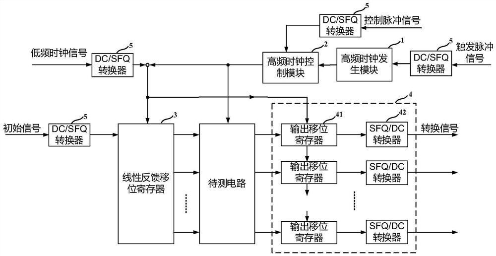
[0073] This embodiment provides a superconducting high-frequency test system, which includes: a high-frequency clock generation module 1 , a high-frequency clock control module 2 , a linear feedback shift register 3 and an output conversion module 4 .
[0074] Specifically, the high-frequency clock generation module 1 is implemented based on a ring oscillator, receives a trigger pulse signal, and outputs a periodic high-frequency clock signal.
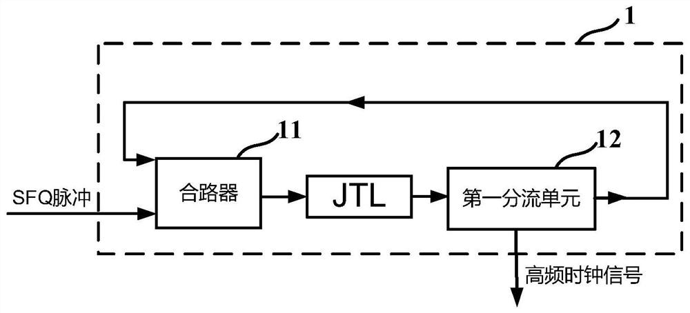
[0075] As an example, such as figure 2 As shown, the high-frequency clock generation module 1 includes a combiner 11 and a first shunt unit 12; the combiner 11 receives a trigger pulse signal and a split clock signal, and outputs a combined clock signal; the first split The unit 12 receives the combined clock signal, outputs two signals identical to the combined clock signal, one is output as the split clock signal, and the other is output as the high-frequency clock signal.
[0076] Such as figure 2 As shown, the combiner 11 and t...
Embodiment 2
[0099] This embodiment provides a superconducting high-frequency test method. In this embodiment, the superconducting high-frequency test method is implemented based on the superconducting high-frequency test system in Embodiment 1. In practical applications, the method can be based on any A system capable of implementing the method is not limited to this embodiment. Include the following steps:
[0100] The high-frequency clock generation module 1 receives the trigger pulse signal and outputs a periodic high-frequency clock signal;
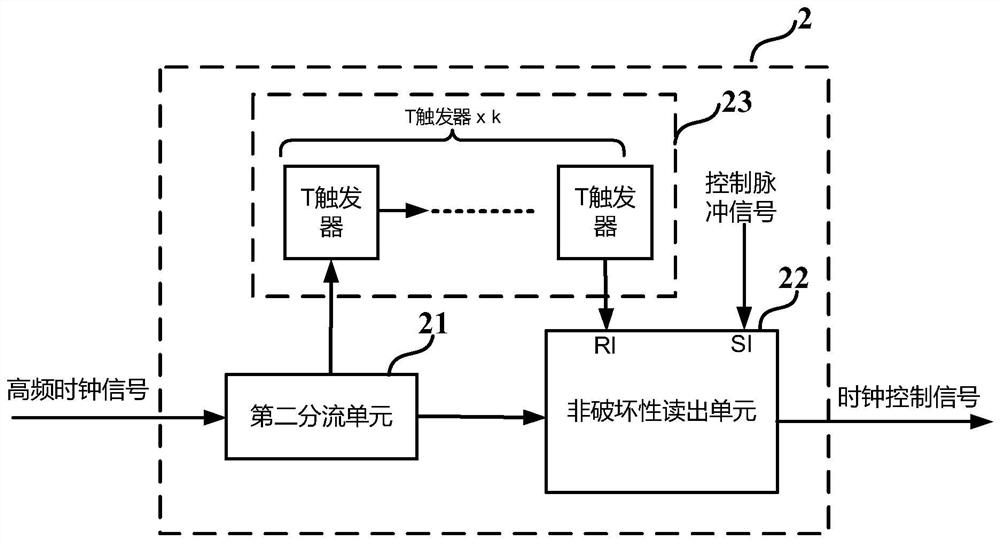
[0101] The high-frequency clock control module 2 receives the control pulse signal, controls the continuity of the high-frequency clock signal, and outputs the high-frequency control clock signal;
[0102] The linear feedback shift register 3 receives an initial signal, sets a non-zero initial state for the linear feedback shift register 3 based on a low-frequency clock signal, and simultaneously outputs the periodicity of multiple preset cycle ...
PUM
 Abstract
Description
Claims
Application Information
 - Generate Ideas
- Intellectual Property
- Life Sciences
- Materials
- Tech Scout
- Unparalleled Data Quality
- Higher Quality Content
- 60% Fewer Hallucinations
Browse by: Latest US Patents, China's latest patents, Technical Efficacy Thesaurus, Application Domain, Technology Topic, Popular Technical Reports.
© 2025 PatSnap. All rights reserved.Legal|Privacy policy|Modern Slavery Act Transparency Statement|Sitemap|About US| Contact US: help@patsnap.com


