Moire fringe-based detection device and detection method

A Moiré fringe and detection device technology, which is applied to measurement devices, optical devices, instruments, etc., can solve the problems of high operation difficulty, complex assembly process, and difficulty in manufacturing accuracy, and achieves cost reduction, convenient use, Adjustable and flexible effects

Active Publication Date: 2021-06-25
CHONGQING UNIV OF TECH
View PDF14 Cites 0 Cited by
  • Summary
  • Abstract
  • Description
  • Claims
  • Application Information

AI Technical Summary

Problems solved by technology

[0003] However, the processing and manufacturing of metrological gratings is relatively difficult. There are a large number of parallel slits of equal width and equal spacing on the grating (scores, thousands or even tens of thousands of lines within 1cm width), which need to be cut on glass or metal-coated It is engraved on the surface, carved with a precision marking machine or obtained by lithographic replication process of evaporative chrome plating on a glass substrate. The distance between adjacent markings is called grating pitch, grating pitch or grating constant. is the benchmark for displacement measurement
The cost of metrology grating is high, and it is very difficult to further improve the manufacturing accuracy
In addition, when assembling as a product, the installation accuracy requirements between the two metering gratings are very high, and the relative position requirements of the assembly used in the design must be met, otherwise the use effect of the product will be seriously affected, which leads to complex assembly process and high difficulty in operation

Method used


Image

  • Moire fringe-based detection device and detection method
  • Moire fringe-based detection device and detection method
  • Moire fringe-based detection device and detection method

Examples


Embodiment Construction

[0032] The specific implementation manners of the present invention will be further described in detail below in conjunction with the accompanying drawings.

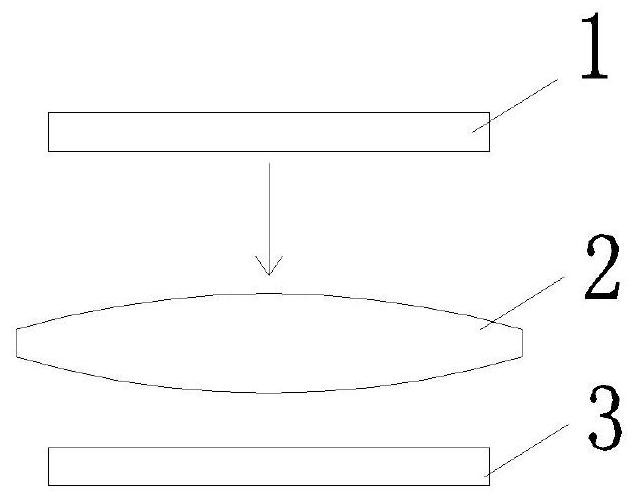
[0033] See figure 2 , a detection device based on Moiré fringes in a specific embodiment, comprising a light source 1 of an area array and a photodetector 3 of an area array, the light source 1 of the area array and the photodetector 3 are arranged in parallel to each other and can be relatively positioned along its own Where the plane is sliding, an imaging lens 2 is arranged in parallel between the light source 1 of the area array and the photodetector 3 , and the light beam emitted by the light source 1 of the area array is imaged on the photodetector 3 after passing through the imaging lens 2 . During implementation, you can choose to set the light source on the sliding carrier, the photodetector and imaging lens are relatively fixed as fixed items, and the vertical distance from the imaging lens to the photodetecto...


PUM


Abstract

The invention relates to a moire fringe-based detection device and detection method. The device comprises a light source of an area array and a photoelectric detector of the area array, the light source and the photoelectric detector are arranged in parallel and can relatively slide along the plane where the light source and the photoelectric detector are located, and an imaging lens is further arranged between the light source and the photoelectric detector in parallel. Light beams emitted by the light source are imaged on the photoelectric detector after passing through the imaging lens, and the light source of the area array is electrically connected with the programming controller so as to control the area array light source to display set content information through the programming controller; The photoelectric detector is electrically connected with the control computer, so that the control computer controls the photoelectric detector to read signals according to a set reading area, and the control computer processes the signals read by the photoelectric detector. Through simple structure replacement and a corresponding method, displacement measurement application of moire fringes can also be realized, a grating and a strict assembly process are not needed to ensure the position of a physical structure, the cost is lower, and the measurement precision is favorably ensured.

Description

technical field [0001] The invention belongs to the technical field characterized by adopting an optical method in physical measurement, and in particular relates to a detection device and a detection method based on Moiré fringes. Background technique [0002] The engineering value of the moiré fringe pattern has been recognized and applied. The most widely used field is the relative displacement measurement of the grating, and there are also applied products such as the grating ruler. In order to improve the measurement accuracy, existing technologies such as: CN101571377A, CN102706373A, CN105627921A, CN106556342A, etc. also researched and innovated the subdivision and measurement methods of grating stripes and image coding. However, the use of Moiré fringes in the current grating scale application products can be found in the attached figure 1 , are carried out by means of a point light source 100, a lens 101, two metering gratings (one is a scale grating 102, and the ot...

Claims


Application Information

Patent Timeline
IPC IPC(8): G01B11/02G01B11/26
CPCG01B11/02G01B11/26
Inventor 彭川黔
Owner CHONGQING UNIV OF TECH
Why Eureka
Try Eureka