Ball valve

A ball valve and valve body technology, applied in the field of pipeline valves, can solve the problems of increased weight and volume of ball valves, inconvenient installation and use, and easy formation of water hammer, so as to improve the response speed of opening and closing, reduce weight and volume, and improve flexibility and convenience. sexual effect

Active Publication Date: 2021-06-25
TIANJIN CHINA NUCLEAR TECH IND CO LTD
View PDF7 Cites 1 Cited by
  • Summary
  • Abstract
  • Description
  • Claims
  • Application Information

AI Technical Summary

Problems solved by technology

[0004] 1. When the ball valve is used in a high-pressure pipeline, because the pressure difference before and after the ball valve is closed is particularly large, especially when the outlet side is zero pressure, the valve ball of the ball valve will be tightly pressed on the driving part under the action of the medium pressure difference , the ball valve needs a large driving torque to open, so it needs to be equipped with a high-power ball valve opening device, which will not only greatly increase the equipment purchase cost, but also increase the weight and volume of the entire ball valve, resulting in inconvenience in installation and use
[0005] 2. If the opening and closing speed of the ball valve is too fast, it is easy to form water hammer, which will cause impact damage to the internal structure of the ball valve, and even make the seal or valve seat loose and affect the sealing and service life of the entire ball valve

Method used


Image

  • Ball valve
  • Ball valve
  • Ball valve

Examples


Embodiment Construction

[0028] The technical solutions of the present invention will be further described in detail below in conjunction with the accompanying drawings and embodiments.

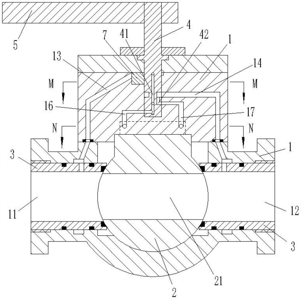
[0029] combine Figure 1 to Figure 6 As shown, the ball valve in this embodiment includes a valve body 1 , a valve ball 2 , a valve seat 3 and a valve shaft 4 .

[0030] An inlet 11, an outlet 12, an inlet channel 13, an outlet channel 14 and a control groove 15 are arranged on the valve body 1, wherein a valve seat 3 is respectively provided at the inlet 11 and the outlet 12, and the valve ball 2 is located on the valve body. The inside of the body 1 and at the same time form a movable sealing connection with the two valve seats 3 through seals.

[0031] A through hole 21 and a control plate 22 are provided on the valve ball 2 . Wherein, the through hole 21 runs through the valve ball 2 in the radial direction, and is used to communicate and cut off the inlet 11 and the outlet 12, and one end of the control plate ...


PUM


Abstract

The invention belongs to the technical field of pipeline valves, and discloses a ball valve which comprises a valve body and a valve ball. The valve body is provided with an inlet, an outlet, an inlet runner, an outlet runner and a control groove, and the valve ball is located in the valve body and provided with a control plate and a through hole. The control plate extends into the control groove to divide the control groove into a first control groove and a second control groove, and the control plate can reciprocate along the control groove to drive the valve ball to rotate relative to the valve body so as to control the communication relation between the through hole and the inlet and the communication relation between the through hole and the outlet. One end of the inlet runner communicates with the inlet, the other end of the inlet runner selectively communicates with the first control groove and the second control groove, one end of the outlet runner communicates with the outlet, and the other end of the outlet runner selectively communicates with the second control groove and the first control groove. The ball valve is used in a high-pressure pipeline, not only is low in manufacturing cost, but also has smaller weight and size, and has higher installation flexibility and use convenience.

Description

technical field [0001] The invention belongs to the technical field of pipeline valves, in particular to a ball valve. Background technique [0002] The opening and closing part of the ball valve is a ball with a through hole, which can achieve the purpose of opening and closing the channel by rotating around the axis perpendicular to the channel. Ball valves have been widely used in petroleum, chemical industry, power generation, papermaking, atomic energy, aviation, rocket and other departments, as well as people's daily life, because of their advantages such as small fluid resistance, simple structure, compactness and reliability, convenient operation, rapid opening and closing, and wide application range. middle. [0003] However, the current traditional structure of the ball valve has the following problems in the process of opening or closing: [0004] 1. When the ball valve is used in a high-pressure pipeline, because the pressure difference before and after the bal...

Claims


Application Information

Patent Timeline
Patent Type & Authority Applications(China)
IPC IPC(8): F16K5/06F16K31/60F16K31/05F16K47/02F16K27/06
CPCF16K5/06F16K5/0647F16K31/60F16K31/055F16K47/02F16K27/067
Inventor 李来滨邵建国杜爱芝
Owner TIANJIN CHINA NUCLEAR TECH IND CO LTD
Why Eureka
Try Eureka