A screw rotating device for automatic tooth removal

A technology of rotating device and screw, applied in the direction of transmission device, slip coupling, belt/chain/gear, etc., can solve the problem of increasing production cost and labor intensity, wire damage of screw and slider, screw rotation accuracy Difficult to control and other problems, to achieve the effect of convenient and effective connection, reduce distance installation accuracy, and ingenious and effective design

Active Publication Date: 2022-06-17
ZHEJIANG CHIXIN IND CO LTD
View PDF0 Cites 0 Cited by
  • Summary
  • Abstract
  • Description
  • Claims
  • Application Information

AI Technical Summary

Problems solved by technology

[0003] However, when the screw motor is actually used, the rotation of the motor shaft has a certain inertia, and the screw tends to over-rotate. If the slider on the screw is stuck by the limit, the over-rotation of the screw will affect the screw opening of the screw and the slider. Cause damage, long-term wear will reduce the accuracy of slider movement, which is very unfavorable to assembly
Especially for large-scale equipment, it needs to be equipped with a motor with greater power as the driving part. Its torque is greater, and the inertia driven by it during rotation is also stronger. The more difficult it is to control the rotation accuracy of the screw, the screw and slider are often easily damaged. Its service life has virtually increased production costs and labor intensity, and this phenomenon needs to be resolved

Method used


Image

  • A screw rotating device for automatic tooth removal
  • A screw rotating device for automatic tooth removal
  • A screw rotating device for automatic tooth removal

Examples


Embodiment 1

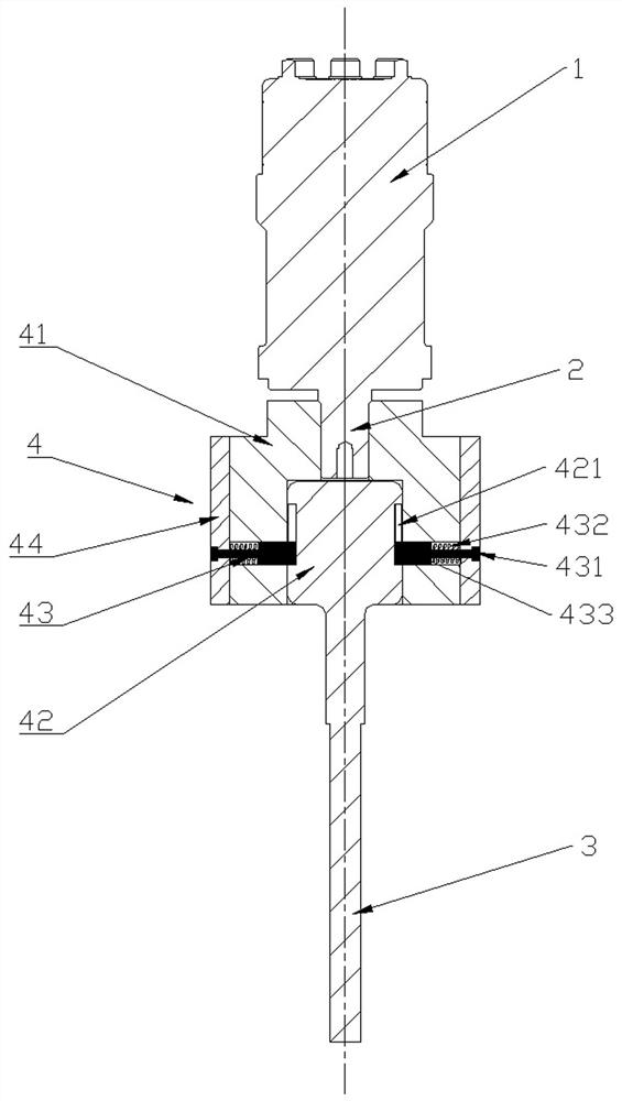
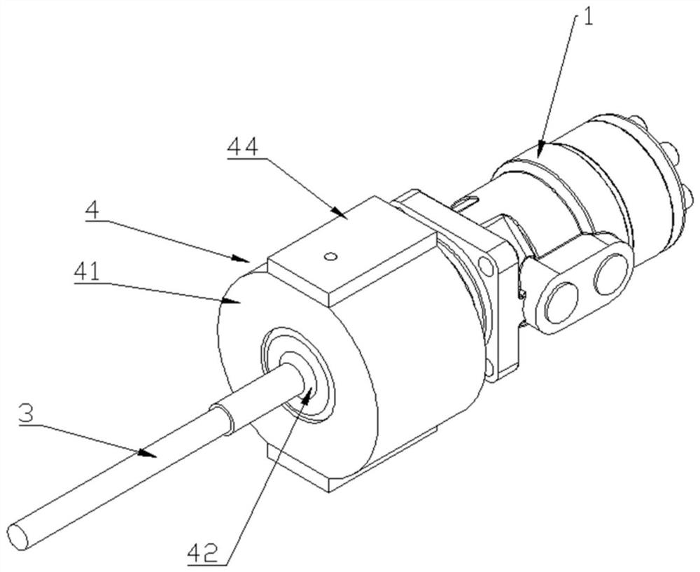
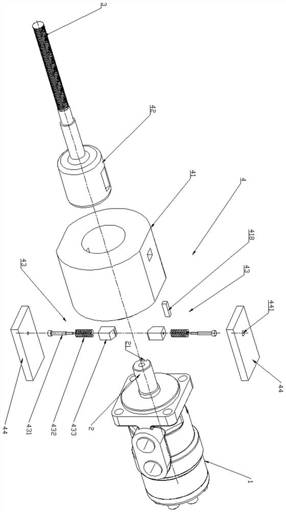
[0040] like Figure 1-9 As shown, this embodiment provides a screw rotating device for automatic tooth removal, including a motor 1, a transmission shaft 2 and a screw 3, and the transmission shaft 2 and the screw 3 are connected by an automatic tooth removal component 4, wherein the automatic tooth removal component 4 includes an outer sleeve 41 and an inner cylinder 42, the outer sleeve 41 is fixedly connected with the transmission shaft 2, the screw 3 is fixedly connected with the inner cylinder 42, and the outer sleeve 41 is sleeved outside the inner cylinder 42 and is relatively fixedly connected by an elastic member 43; In the normal state, the motor 1 drives the transmission shaft 2 to rotate, which in turn drives the outer sleeve 41, the inner cylinder 42, and the screw 3 to rotate synchronously. When the rotation of the screw 3 is limited, the inner cylinder 42 and the outer sleeve 41 are disconnected from the fixed connection state. , the outer sleeve 41 can slip and...

Embodiment 2

[0060] like Figure 10-11 , Compared with the first embodiment, the difference between this embodiment is the connection method between the outer sleeve 41 and the transmission shaft 2 . In this embodiment, the end of the transmission shaft 2 is provided with a shaft end through hole (not shown in the figure), the coupling section 411 is provided with a radial coupling through hole 415 correspondingly, and the pin rod 419 is provided to pass through the shaft end The through hole and the coupling through hole 415 are used to realize the axial and circumferential fixed coupling of the transmission shaft 2 and the outer sleeve 41 . The pressure plate 44 can be additionally installed on the outer sleeve 41 by screws, and the outer sleeve 41 is provided with a flat surface to facilitate the installation of the pressure plate; when the transmission shaft 2 and the outer sleeve 41 are connected by pins, the pin 419 can be provided with threads, and the pressure plate Corresponding ...

Embodiment 3

[0063] This embodiment provides a specific application scenario of the screw rotating device for automatic tooth extraction.

[0064] like Figure 12-13 As shown in the figure, in this embodiment, the screw rotating device for automatic tooth removal is applied in the field of mold processing, but it is not limited to this field. To be connected, it is necessary to rotate the screw 3 to drive the insertion device 6 to move forwards and backwards as a whole, so that other components connected to the insertion device 6 can move forwards and backwards to assemble with the main device 9 .

[0065] The mounting seat 5 is an annular structure with an inner circle and an outer square, and the middle part is an axial mounting through hole 51. The mounting seat 5 is provided with a mounting screw hole 52 corresponding to the motor 1. The mounting seat 5 and the motor 1 are fixedly connected by bolts. 2 is connected to the automatic tooth removal assembly 4 through the installation thr...


PUM


Abstract

The invention provides a screw rotating device for automatic tooth removal, which belongs to the technical field of manufacturing equipment. It includes a motor, a transmission shaft and a screw, and the transmission shaft and the screw are connected by an automatic tooth removal component, wherein the automatic tooth removal component includes an outer sleeve and an inner sleeve, the outer sleeve is fixedly connected to the transmission shaft, and the screw is fixedly connected to the inner cylinder. The outer sleeve is set outside the inner cylinder and is relatively fixedly connected to the inner cylinder through elastic parts; in normal state, the motor drives the transmission shaft to rotate, which in turn drives the outer sleeve, inner cylinder and screw to rotate synchronously. When the screw rotation is limited, the inner The sleeve and the outer sleeve are separated from the fixed connection state, and the outer sleeve can slide and rotate outside the inner sleeve to realize the automatic tooth removal of the screw. In the present invention, the screw and the transmission shaft are not fixedly connected, but relatively fixedly connected through the automatic detooth assembly. Normally, the screw and the transmission shaft rotate synchronously. When the rotation of the screw is limited, the screw and the transmission shaft are disconnected, and the screw will not Over-rotate with the drive shaft to protect the screw.

Description

technical field [0001] The invention belongs to the technical field of manufacturing equipment, relates to a displacement transmission structure, and in particular relates to a screw rotating device for automatic tooth removal. Background technique [0002] In modern automated machinery and equipment, the movement of objects is often involved, and the displacement is usually driven by driving parts such as motors and cylinders. For example, a screw motor is a type of motor that converts the rotary motion of the motor into linear motion. It includes a motor body and a screw assembly. The screw assembly includes a screw and a slider. The rotating shaft of the motor body is connected to the screw through a coupling, thereby driving the screw to rotate. sports. In the existing screw motor, the shaft and the screw are connected by a coupling, and the shaft and the screw rotate synchronously. [0003] However, when the screw motor is actually used, the rotation of the motor shaf...

Claims


Application Information

Patent Timeline
Patent Type & Authority Patents(China)
IPC IPC(8): F16H25/20F16D7/04
CPCF16H25/2021F16H25/2025F16D7/048
Inventor 翁溧溧朱将来张吕周周武斌
Owner ZHEJIANG CHIXIN IND CO LTD
Why Eureka
Try Eureka