Siphon water-permeable brick body and paving method thereof
A brick body and siphon technology, which is applied to pavement details, pavements paved with prefabricated blocks, roads, etc., can solve the problems of reduced conductivity and poor external pressure resistance, so as to improve the external pressure resistance and solve the problem of resistance to external pressure. Effects of poor external pressure capability and reduced conductivity
- Summary
- Abstract
- Description
- Claims
- Application Information
AI Technical Summary
Problems solved by technology
Method used
Image

Examples
Embodiment 1
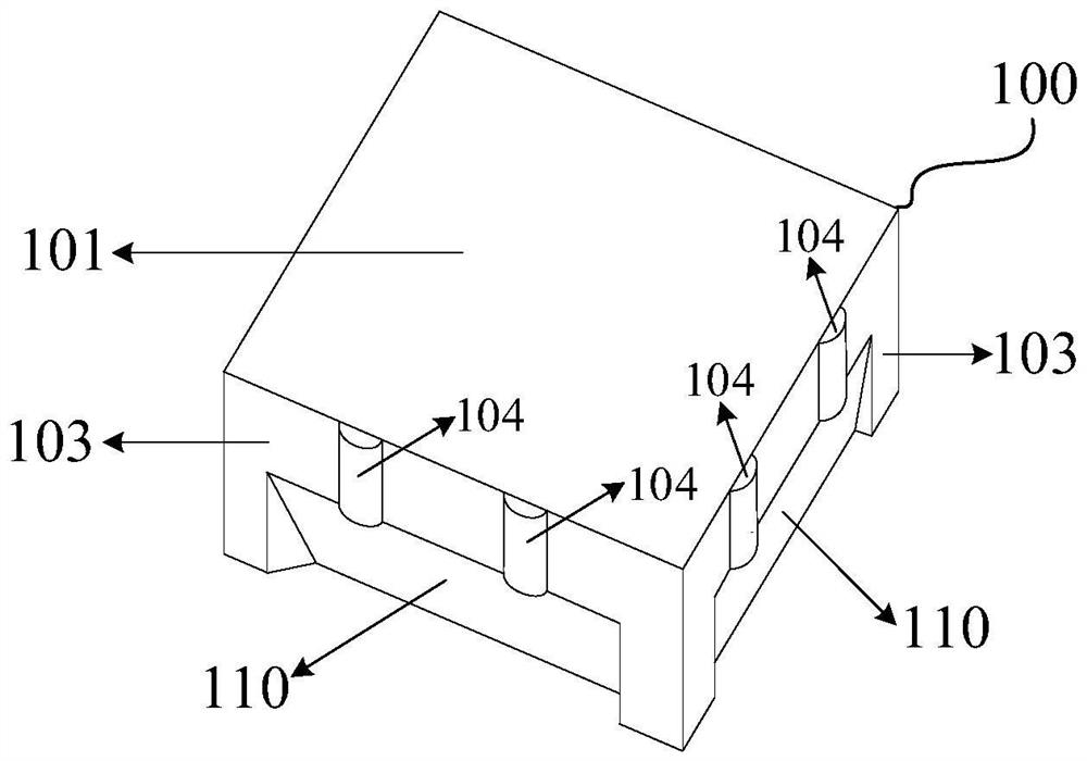
[0025] Please refer to figure 1 , which shows a schematic structural view of a siphon permeable brick body provided by an exemplary embodiment of the present invention.
[0026] Such as figure 1 As shown, the siphon permeable brick body includes a brick body 100, and the brick body 100 includes an upper brick surface 101, a lower brick surface 102 and four side brick surfaces 103, wherein, due to occlusion, the lower brick surface 102 and the remaining sides Not all numbers of the brick surface 103 are shown in the figure.
[0027] Such as figure 1 As shown, each side brick surface 103 is provided with a seam gap 104 and a side cut space 110 .
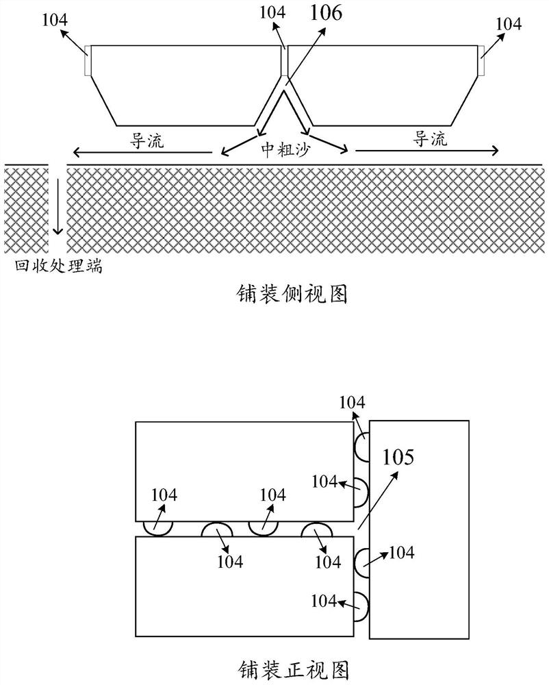
[0028] Such as figure 2 In the front view of the pavement shown, the seam gap 104 is used to form a permeable gap 105 when the siphon permeable bricks are spliced; figure 2 In the side view of the pavement shown, the side cut space 110 is used to form the water storage space 106 when the siphon permeable bricks are spliced.
[...
Embodiment 2
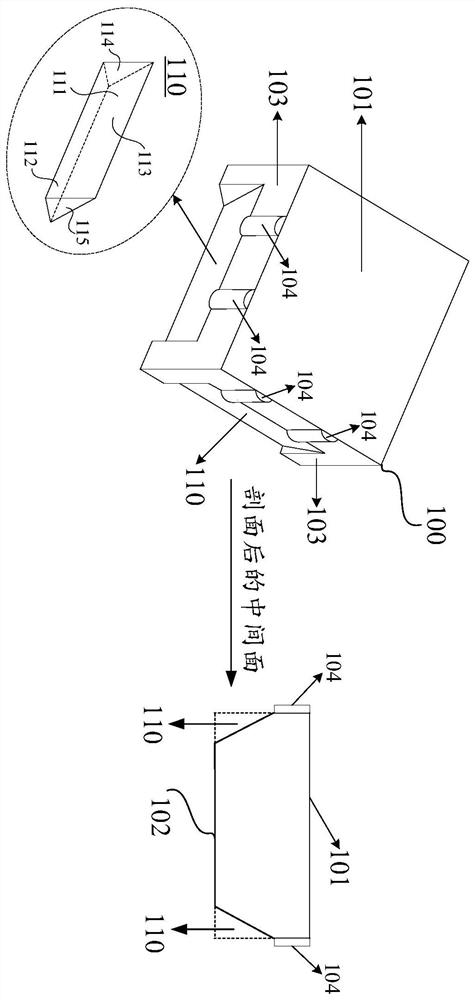
[0033] Please refer to image 3 , which shows a schematic structural view of a siphon permeable brick body provided by another exemplary embodiment of the present invention.
[0034] exist figure 1 shown in the schematic diagram above, by image 3 To further describe the siphon permeable brick body, the side cut space 110 is a triangular column structure, and the side cut space 110 includes a first side 111 , a second side 112 , a third side 113 , an upper bottom 114 and a lower bottom 115 .
[0035] The first side 111 of the side cutting space 110 is perpendicular to the upper brick surface 101, the second side 112 of the side cutting space 110 is on the same plane as the lower brick surface 102, the third side 113 of the side cutting space 110 is an inclined surface, the first side 111 and the second side The two sides 112 are vertical.
[0036] In addition, in the embodiment of the present invention, the brick body material is also limited. Among them, the upper brick s...
Embodiment 3
[0044] Please refer to Figure 4 , Figure 4 A schematic flow chart of a siphon permeable brick paving method shown in an exemplary embodiment of the present invention is shown, the method includes:
[0045] Step 401, laying a sand and gravel cushion on the soil layer, the thickness of the sand and gravel cushion is determined according to the type of road.
[0046] Among them, different road types have different requirements for the hardness of the road surface. For example, the hardness required for the sidewalk is lower than that for the road surface of the road. Therefore, in the embodiment of the present invention, the thickness of the sand and gravel cushion is determined according to the road type.
[0047] Wherein, the soil layer refers to the bottom foundation, which may be the soil layer of artificial burial, or the soil layer formed under natural conditions.
[0048] In a possible implementation manner, step 401 may be divided into the following contents.
[004...
PUM
 Abstract
Description
Claims
Application Information
 - R&D
- Intellectual Property
- Life Sciences
- Materials
- Tech Scout
- Unparalleled Data Quality
- Higher Quality Content
- 60% Fewer Hallucinations
Browse by: Latest US Patents, China's latest patents, Technical Efficacy Thesaurus, Application Domain, Technology Topic, Popular Technical Reports.
© 2025 PatSnap. All rights reserved.Legal|Privacy policy|Modern Slavery Act Transparency Statement|Sitemap|About US| Contact US: help@patsnap.com