Eureka AIR delivers breakthrough ideas for toughest innovation challenges, trusted by R&D personnel around the world.

Rotational flow thermal vibration drying machine and rotational flow thermal vibration drying system

A drying machine and drying technology, which is applied in chemical instruments and methods, chemical/physical processes, and methods for granulating raw materials. Cleaning and other problems, to achieve the effect of less floor space, compact equipment, and simple equipment

Pending Publication Date: 2021-06-25
山东驰盛新能源设备有限公司
View PDF5 Cites 3 Cited by
  • Summary
  • Abstract
  • Description
  • Claims
  • Application Information

AI Technical Summary

Problems solved by technology

[0011] Therefore, in view of this situation, it is urgent to design and produce a cyclone thermal vibration drying machine and a cyclone thermal vibration drying system to solve the need to reduce the exhaust gas at the outlet of the drying chamber in the prior art. It is difficult, and the heat exchange surface of the dryer is easy to scale and difficult to clean

Method used


Image

  • Rotational flow thermal vibration drying machine and rotational flow thermal vibration drying system
  • Rotational flow thermal vibration drying machine and rotational flow thermal vibration drying system
  • Rotational flow thermal vibration drying machine and rotational flow thermal vibration drying system

Examples


Embodiment Construction

[0050] In order to make the object, technical solution and advantages of the present invention clearer, the present invention will be further described in detail below in conjunction with the accompanying drawings and specific embodiments. It should be understood that the specific embodiments described here are only used to explain the present invention, not to limit the present invention.

[0051] Example of turbo thin layer dryer

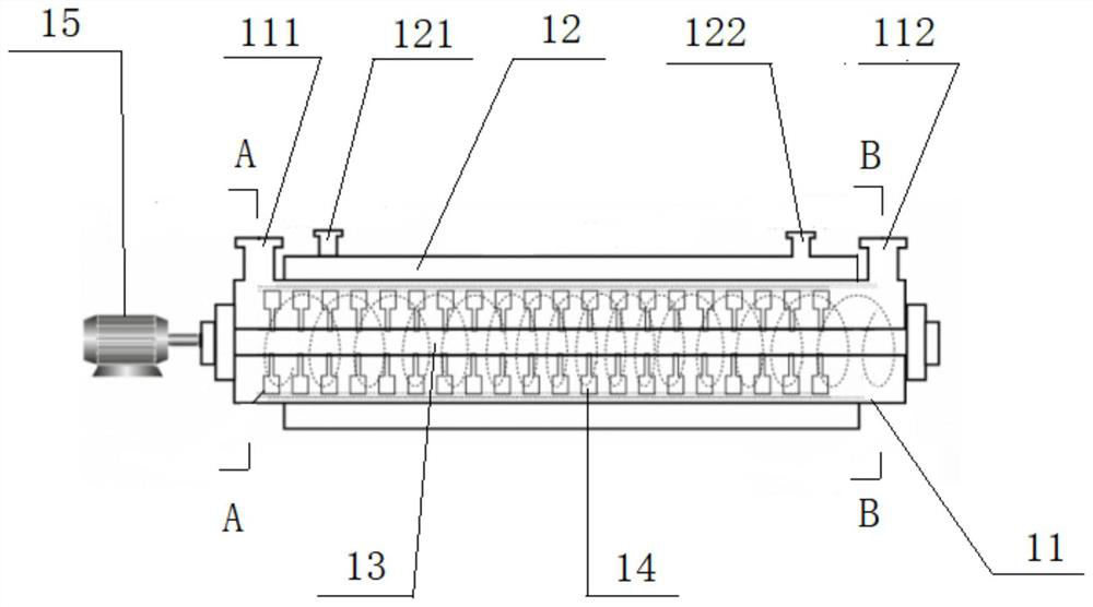
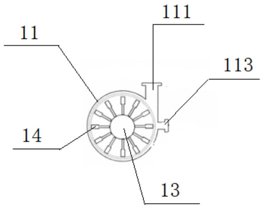
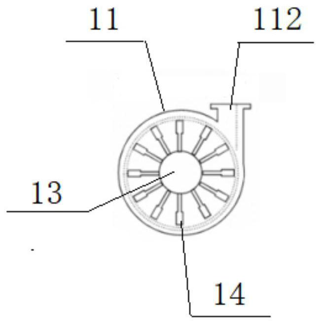
[0052] like Figure 1 to Figure 3 As shown, the solution provides a swirling heat vibration drying machine 1, the drying machine 1 is mainly composed of a drying chamber 11, a heat source jacket 12, a paddle 14, a rotating shaft 13, a material inlet 111, and a material outlet 112 , air inlet 113, heat source inlet 121, heat source outlet 122 and other structures.

[0053] The drying chamber 11 is a hollow structure, and one end of the drying chamber 11 is provided with a material inlet 111 and an air inlet 113 , and the other end is provided wit...


PUM


Abstract

The invention relates to the technical field of wet sludge drying, in particular to a rotational flow thermal vibration drying machine and a rotational flow thermal vibration drying system. The rotational flow thermal vibration drying machine comprises: a hollow drying chamber, wherein one end of the drying chamber is provided with a feeding port and an air inlet, and the other end of the drying chamber is provided with a discharging port; a heat source jacket which is arranged around the outer side of the drying chamber, wherein a medium serving as a heat source circulates in the heat source jacket, and a heat source outlet and at least one heat source inlet are formed in the heat source jacket; a rotating shaft which is arranged in the middle of the drying chamber and penetrates through the two ends of the drying chamber, wherein a driving motor used for driving the rotating shaft to rotate is arranged on the outer side of the drying chamber; and paddles which are mounted on the rotating shaft. The drying machine has a self-cleaning capability, so that the wall sticking phenomenon is avoided; The safe operation of the system is ensured by high-degree inerting circulation; and the drying machine is high in heat exchange efficiency, high in heat transfer speed and high in sludge drying speed. When the drying system is used, irritant gas cannot be discharged to the periphery, and secondary pollution to air is avoided.

Description

technical field [0001] The invention relates to the technical field of wet sludge drying, in particular to a cyclone thermal vibration drying machine and a cyclone thermal vibration drying system. Background technique [0002] With the expansion of my country's industrial scale and the acceleration of urbanization, the output and treatment of sludge have increased year by year. my country's sludge is mainly composed of municipal sludge and industrial sludge. According to the statistics of the Ministry of Environmental Protection of China, the output of municipal sludge in my country in 2018 was 30 million tons, and the output of industrial sludge has exceeded 10 million tons. Calculated with a growth rate of 11.49%, the total sludge output will exceed 100 million tons in 2024. As a product of sewage treatment, sludge contains a large number of harmful substances such as bacteria, viruses, and microbial eggs. Without effective treatment and disposal, sludge can easily pollute...

Claims


Application Information

Patent Timeline
Patent Type & Authority Applications(China)
IPC IPC(8): C02F11/00C02F11/13B01D50/00B01D45/12B01J2/00
CPCC02F11/00C02F11/13B01D45/12B01J2/00C02F2303/06B01D50/20
Inventor 张振
Owner 山东驰盛新能源设备有限公司
Why Eureka
Eureka Blog
Learn More