Molding-assisted movable production device for steel skeleton building materials
A technology for auxiliary molding and production equipment, which is applied in the direction of lighting equipment, lighting equipment, lighting equipment components, etc., can solve problems such as low error tolerance, offset, and inability to move, so as to meet work requirements, increase clamping length, The effect of increasing the fault tolerance rate
- Summary
- Abstract
- Description
- Claims
- Application Information
AI Technical Summary
Problems solved by technology
Method used
Image

Examples
Embodiment 1
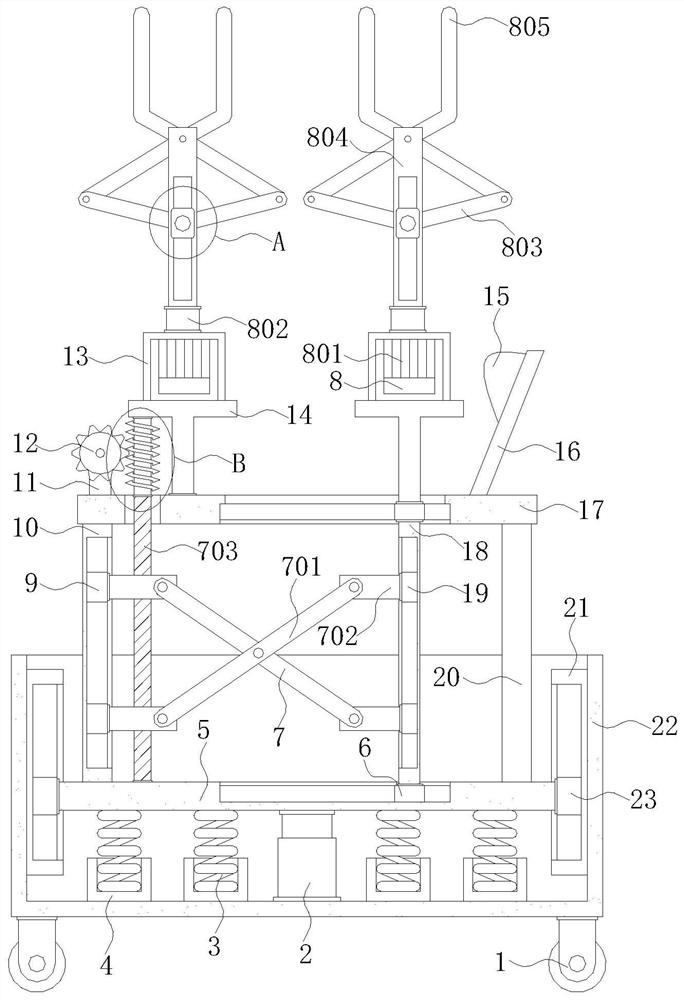
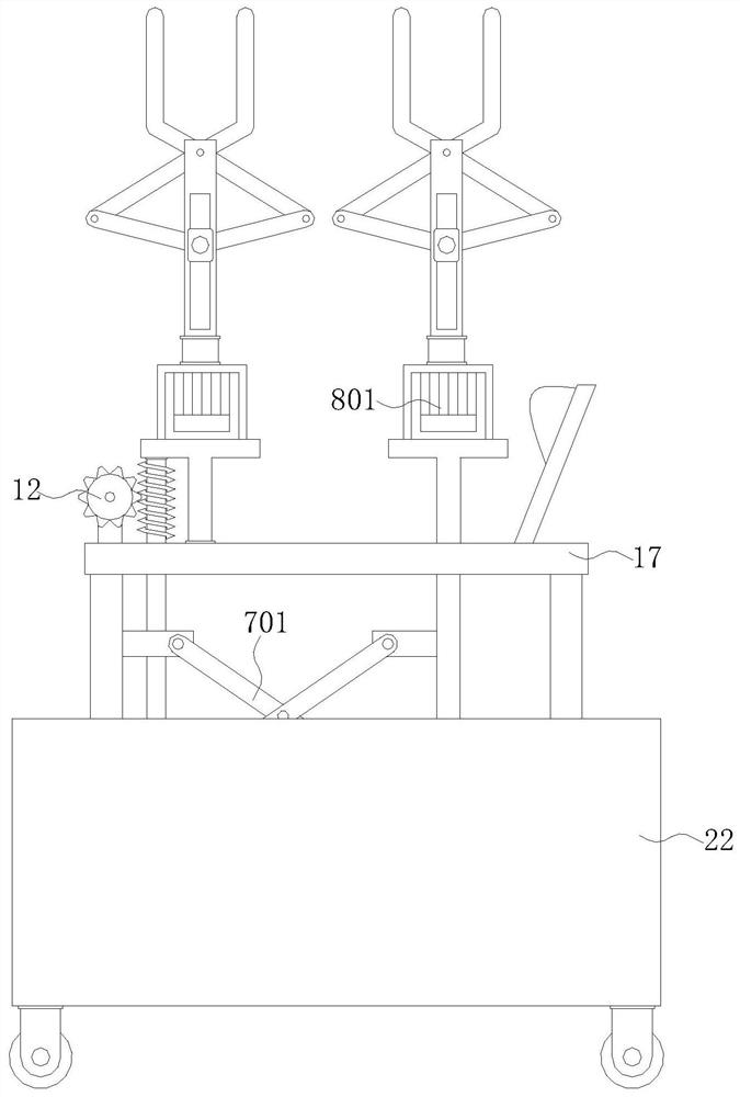
[0028] see Figure 1-6 , a movable production device for auxiliary forming of steel skeleton building materials, including a work box 22, a roller 1 is installed on the bottom of the work box 22 for rotation, a hydraulic rod 2 is welded and installed on the inner bottom of the work box 22, and the inside of the work box 22 is set There is a base plate 5, the telescopic end of the hydraulic rod 2 is welded to the bottom of the base plate 5, and the top of the base plate 5 is welded with a first side frame 10 and a second side frame 20, and the first side frame 10 and the second side frame The top of frame 20 is welded and installed with top plate 17, and the inside of top plate 17 and base plate 5 is all provided with chute, and the inside of chute on top plate 17 and base plate 5 is all slidably installed with first slide block 6, and first slide block 6 is installed on top plate 17. The bottom of 6 is welded and installed with auxiliary plate 18, and the free end of auxiliary...
Embodiment 2
[0032] see Figure 1-6, on the basis of Embodiment 1, the push-type expansion mechanism 7 includes a push rod 701, a fixed block 702, a threaded thick rod 703, a first motor 704 and a worm 705, and the phase of the second slider 9 and the third slider 19 The adjacent side walls are welded with fixed blocks 702, the top of the base plate 5 is rotated with a threaded thick rod 703, the top of the top plate 17 is provided with a hole, and the free end of the threaded thick rod 703 extends through the hole on the top plate 17 and extends to the top plate 17 outside, the top of threaded thick rod 703 is welded with worm screw 705, the free end of worm screw 705 is installed with the bottom of T-shaped plate 14, and the fixed block 702 on the second slide block 9 is threadedly installed with threaded thick rod 703, and worm screw 705 The gears on the top and the gears on the gear plate 12 are meshed. The rear outer wall of the positioning block 11 is fixed with a first motor 704. Th...
Embodiment 3
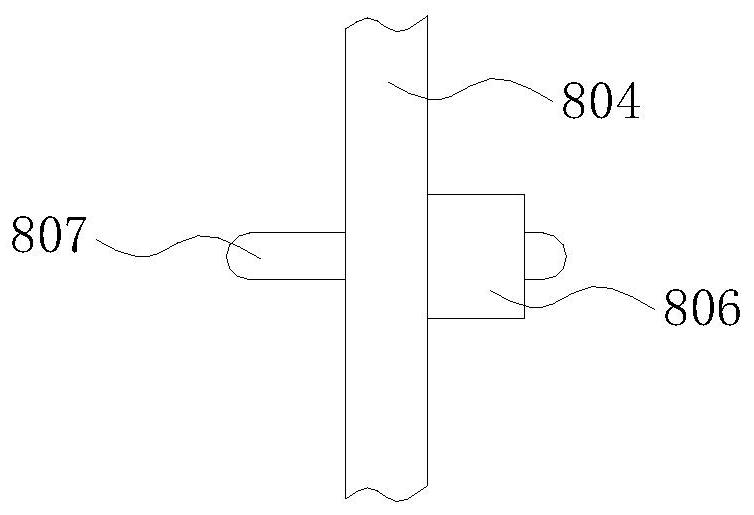
[0034] see Figure 1-6 , on the basis of Embodiment 1, the clamping turning mechanism 8 includes a second motor 801, a thick rotating rod 802, a first clamping rod 803, a riser 804, a second clamping rod 805, a sliding block 806 and a metal rod 807, the top of the first slider 6 on the top plate 17 is welded with a T-shaped plate 14, the T-shaped plate 14 on the first slider 6 and the T-shaped plate 14 on the top plate 17 are located on the same horizontal plane, and the two T-shaped plates The top of 14 is all welded with supporting frame 13, and the inner top of two groups of supporting frames 13 is all fixedly installed with second motor 801, and the top of two groups of supporting frames 13 is all rotatably installed with rotating thick rod 802, and the top of rotating thick rod 802 A riser 804 is welded and installed, and the front outer wall of the riser 804 is provided with a moving groove, and a sliding block 806 is slidably installed inside the moving groove on the ri...
PUM
 Abstract
Description
Claims
Application Information
 - R&D
- Intellectual Property
- Life Sciences
- Materials
- Tech Scout
- Unparalleled Data Quality
- Higher Quality Content
- 60% Fewer Hallucinations
Browse by: Latest US Patents, China's latest patents, Technical Efficacy Thesaurus, Application Domain, Technology Topic, Popular Technical Reports.
© 2025 PatSnap. All rights reserved.Legal|Privacy policy|Modern Slavery Act Transparency Statement|Sitemap|About US| Contact US: help@patsnap.com