Tubular part forming method and tubular part forming device

A technology of parts and tube shapes, which is applied in the field of tube parts forming methods and devices, can solve problems such as the lack of research on liquid filling forming technology, achieve good development potential, improve material forming performance, and reduce the hydraulic tonnage of equipment

Inactive Publication Date: 2021-06-25
BEIHANG UNIV
View PDF11 Cites 0 Cited by
  • Summary
  • Abstract
  • Description
  • Claims
  • Application Information

AI Technical Summary

Problems solved by technology

At present, there are few researches on the liquid-filled forming technology of superalloy tubular parts

Method used


Image

  • Tubular part forming method and tubular part forming device
  • Tubular part forming method and tubular part forming device
  • Tubular part forming method and tubular part forming device

Examples


Embodiment 1

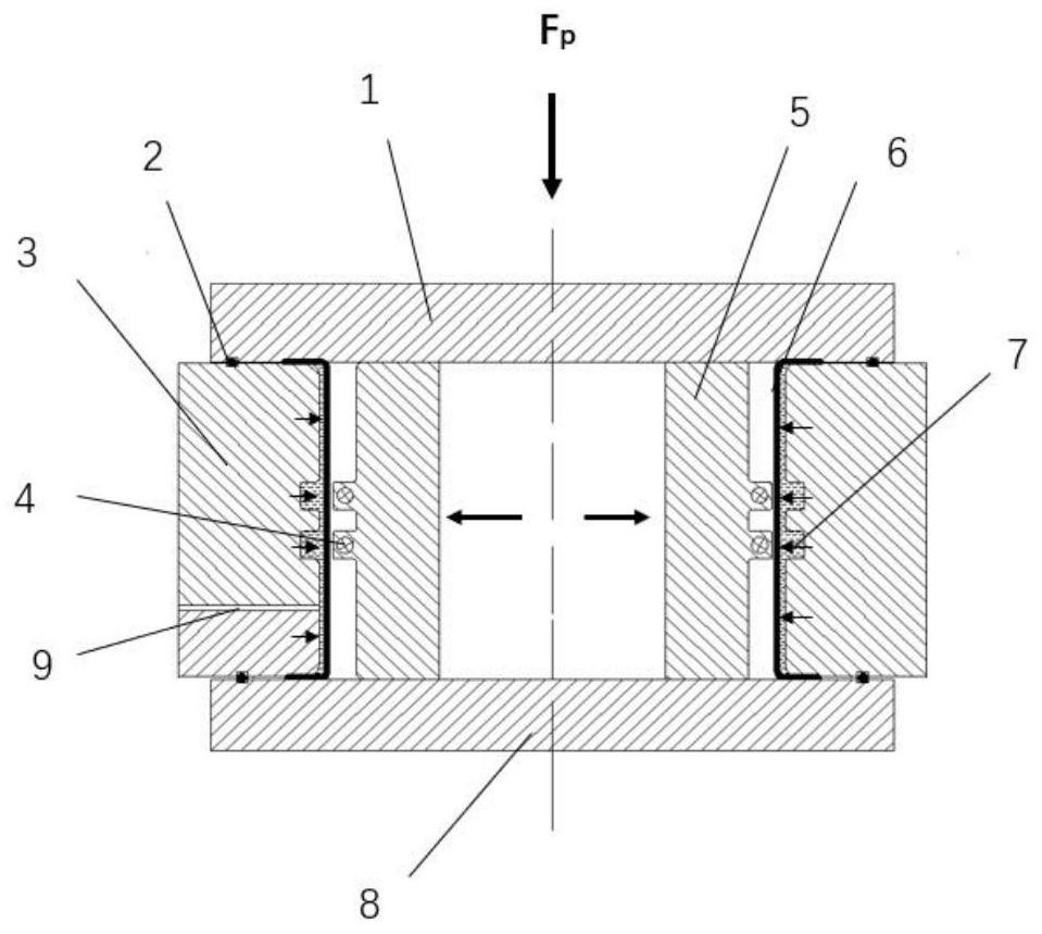
[0039] A tubular part forming device, comprising an upper backing plate 1, a lower backing plate 8, a rigid die 3 and a mold insert 5, wherein the upper backing plate 1 and the lower backing plate 8 are arranged in parallel from top to bottom, and the mold insert 5 and the rigid die 3 are respectively vertically arranged between the upper backing plate 1 and the lower backing plate 8, and the cavity of the rigid die 3 matches the protrusion of the mold insert 3, and the cavity side of the rigid die 5 A liquid chamber cavity 7 is provided, a liquid inlet 9 is provided at the bottom, and a heating ring 4 is provided in the protrusion of the mold insert.

[0040] In this embodiment, sealing rings 2 are respectively arranged between the rigid die 3 and the upper backing plate 1 and the lower backing plate 8 .

Embodiment 2

[0042] The part forming method using the tubular part forming device provided in the above-mentioned embodiment 1 comprises the following steps:

[0043] 1) Inspect the material grade, state, specification and surface quality of the parts through the bill of materials and measuring tools;

[0044] 2) According to the required size, the material of the part is rolled and welded, and the tolerance is 0-0.5mm;

[0045]3) Carry out cutting treatment on the tube billet according to the need, inspect the outer dimension and surface quality of the tube billet after cutting, and then put it into a vacuum heat treatment furnace for annealing treatment;

[0046] 4) After annealing, clean the inner and outer surfaces of the tube blank and the oil stains on the mold surface with a cotton rag;

[0047] 5) Flanging the tube blank according to the preset flanging forming process;

[0048] 6) Clean the key surface and the oil stains on the mold surface with a cotton rag, and check the key d...


PUM


Abstract

A tubular part forming device comprises an upper padding plate, a lower padding plate, a rigid female die and a die insert. The upper padding plate and the lower padding plate are arranged in parallel, the die insert and the rigid female die are perpendicularly arranged between the upper padding plate and the lower padding plate respectively, a rigid female die cavity is matched with a protrusion of the die insert, a fluid medium cavity is formed in one side of the rigid female die cavity, a medium inlet is formed in the bottom of the rigid female die, and a heating ring is arranged in the protrusion of the die insert. Meanwhile, the invention further provides a tubular part forming method adopting the device. According to the method and the device, the application range of a hydraulic forming technology is greatly widened, wide prospects are achieved, the interface bonding strength of the inner layer and the outer layer of a composite tubular part can be improved through the two-way pressure of the die insert and a low-pressure medium, and good development potential is achieved.

Description

technical field [0001] The invention relates to the technical field of metal plastic forming, and more specifically relates to a method and a device for forming a tubular part. Background technique [0002] Superalloys are important metal materials necessary for modern aero-engines, gas turbines and rocket engines. With the development of a new generation of aero-engines towards integration, light weight, long life and high reliability, a series of superalloy hollow components have emerged. Their outstanding features The overall structure, complex shape, small features, high-precision and high-temperature alloy materials have high strength, significant work hardening, and difficulty in cold forming. These characteristics coexist, making the manufacture of such components extremely difficult, and it has become a major technical key to be solved urgently. For example, typical parts such as confluence rings and sealing rings in aero-engines have complex and small internal cavit...

Claims


Application Information

Patent Timeline
Patent Type & Authority Applications(China)
IPC IPC(8): B21D26/033B21D26/047B21D37/16
CPCB21D26/033B21D26/047B21D37/16
Inventor 郎利辉张弛烨郭庆磊
Owner BEIHANG UNIV
Why Eureka
Try Eureka