Fluorescent body positioning device applied in puncture operation or abdominal operation
A technology of positioning device and phosphor, applied in the field of medical devices, can solve the problems of cumbersome operation, inconvenient operation, easy to fall off when the lesion is removed, etc.
- Summary
- Abstract
- Description
- Claims
- Application Information
AI Technical Summary
Problems solved by technology
Method used
Image
Examples
Embodiment 1
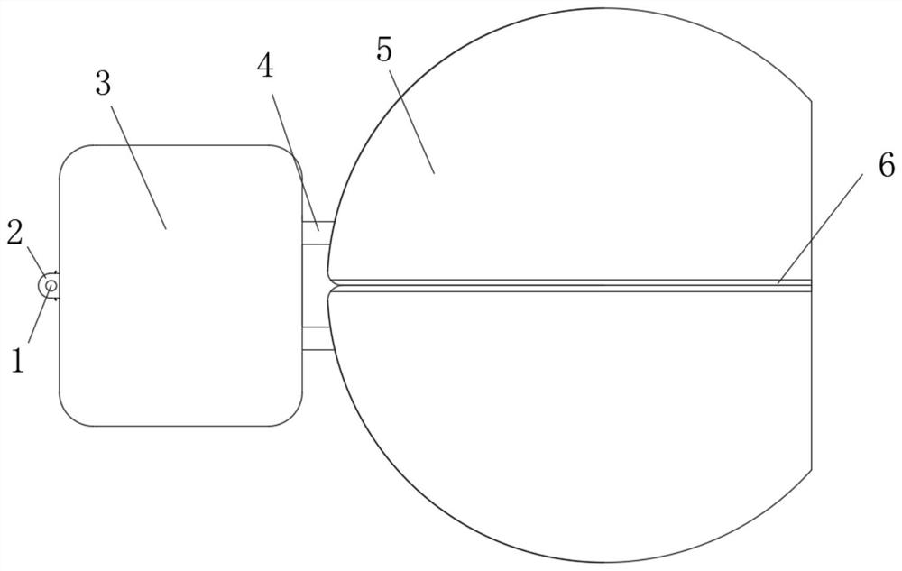
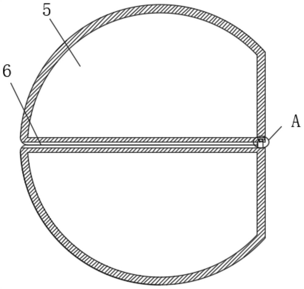
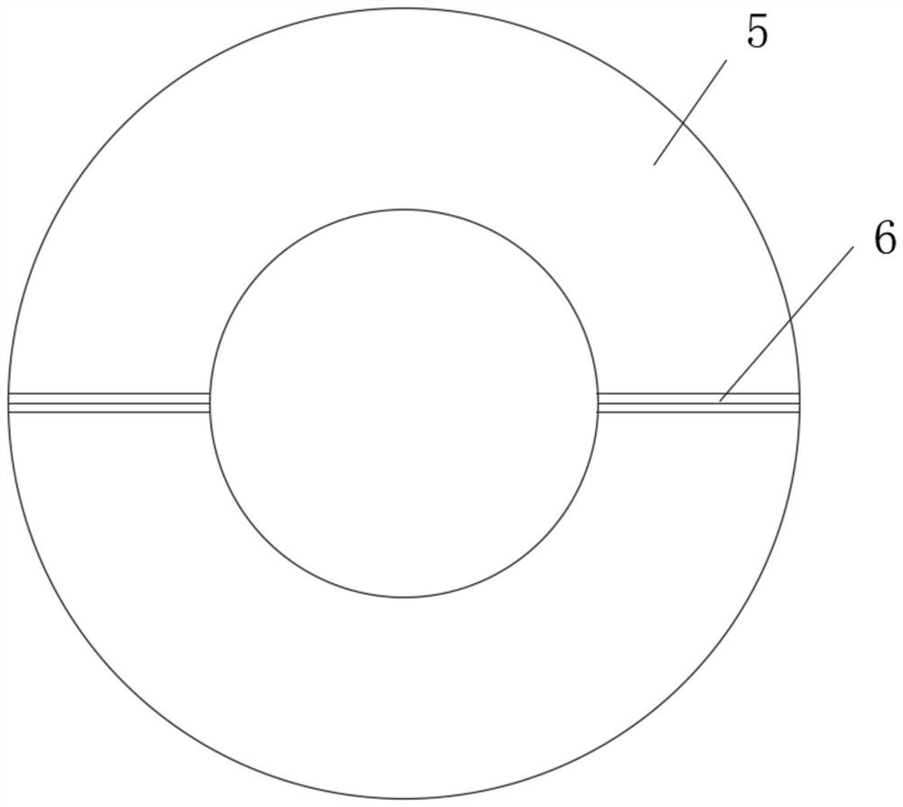
[0031] refer to Figure 1-7 , a fluorescent body positioning device for positioning by puncture surgery or abdominal surgery, comprising a control box 3, two symmetrically arranged rotating shafts 16 are rotatably connected to the inner walls on both sides of the control box 3, and the outer wall of the rotating shaft 16 is fixedly sleeved with a rotating rod 4 One side of the control box 3 is provided with two symmetrically arranged through holes 17, one end of the rotating rod 4 passes through the through holes 17 and is fixedly connected with the phosphor positioning device body 5, and a useful As for the engaging component that engages the two phosphor positioning device bodies 5, the control box 3 is provided with a control component that controls the opening or closing of the two phosphor positioning device bodies 5, and the control box 3 is far away from the through hole 17. The side inner wall is provided with a push assembly for pushing the control assembly, and the t...
Embodiment 2
[0033]This embodiment is improved on the basis of Embodiment 1: the snap-fit assembly includes a fixed block 13 fixedly connected to the top of the phosphor positioning device body 5 located below and a first block set at the bottom of the phosphor positioning device body 5 located above. Draw-in groove 9, one side of fixed block 13 is provided with installation groove 8, and the bottom inner wall of installation groove 8 is slidably connected with the first block 10 that engages with first draw-in groove 9, and one end of first block 10 and installation One side of the inner wall of the slot 8 is fixedly connected with the same first spring 7, the control assembly includes a spur gear 14 fixedly sleeved outside the rotating shaft 16, the two spur gears 14 are meshed, and the top inner wall and the bottom inner wall of the control box 3 are fixed. A second slide rail 19 is connected, and the second slide rail 19 is slidably connected with a second slide block 18 near the spur...
Embodiment 3
[0035] This embodiment is improved on the basis of Embodiment 1: one side of the vertical plate 32 is slidably connected with a bump 29, and the end of the bump 29 away from the pull plate 27 is fixedly connected with a second push plate 30, and the second push plate 30 Two tension springs 31 symmetrically arranged are fixedly connected between the side close to the vertical plate 32, the bottom side of the projection 29 is in conflict with the top side of the pull plate 27, and the bottom of the first clamping block 10 is fixedly connected. There is a first slider 12, the bottom inner wall of the installation groove 8 is fixedly connected with a first slide rail 11, the first slide rail 11 is slidably connected with the first slider 12, and the control rod 2 is located at the top and bottom of one end outside the control box 3 Both of them are fixedly connected with the limiting block 22 , and the sides of the two phosphor positioning device bodies 5 close to each other are fi...
PUM
 Abstract
Description
Claims
Application Information
 - R&D
- Intellectual Property
- Life Sciences
- Materials
- Tech Scout
- Unparalleled Data Quality
- Higher Quality Content
- 60% Fewer Hallucinations
Browse by: Latest US Patents, China's latest patents, Technical Efficacy Thesaurus, Application Domain, Technology Topic, Popular Technical Reports.
© 2025 PatSnap. All rights reserved.Legal|Privacy policy|Modern Slavery Act Transparency Statement|Sitemap|About US| Contact US: help@patsnap.com


