Rack system for inserting electrical printed circuit boards

A technology of assembly system and printed circuit, applied in the direction of electrical components, electrical equipment structural parts, electrical equipment housing/cabinet/drawer, etc., to improve the effect of clamping or holding and electrical contact

Inactive Publication Date: 2003-12-03
RITTAL RES ELECTRONICS SYST GMBH & CO KG
View PDF3 Cites 0 Cited by
  • Summary
  • Abstract
  • Description
  • Claims
  • Application Information

AI Technical Summary

Problems solved by technology

The disadvantage of this device is that it requires the components to have a precise fit
Furthermore, no additional elements are provided to create an electrically protective contact between the front side plate and the transverse connecting rail

Method used


Image

  • Rack system for inserting electrical printed circuit boards
  • Rack system for inserting electrical printed circuit boards
  • Rack system for inserting electrical printed circuit boards

Examples


Embodiment Construction

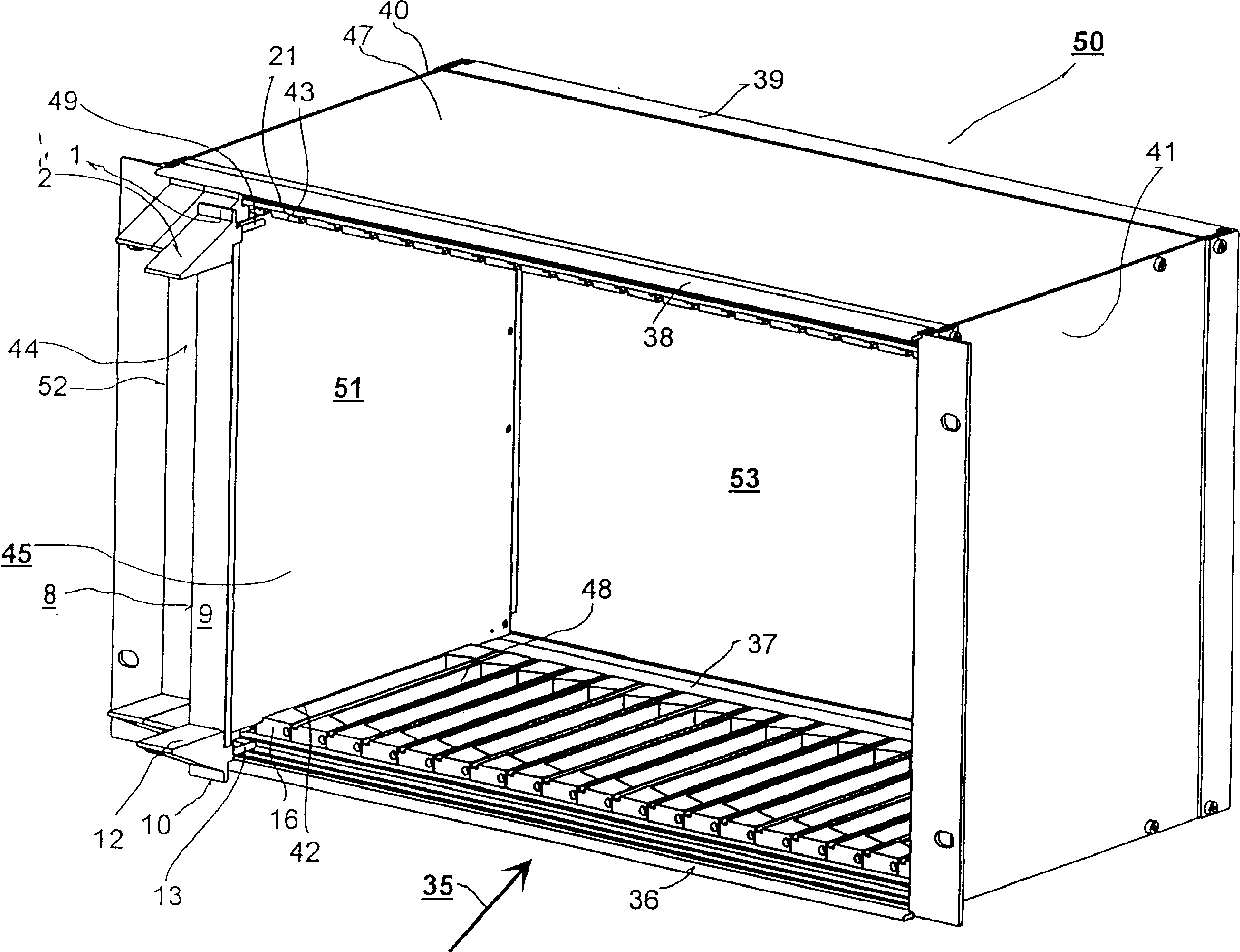
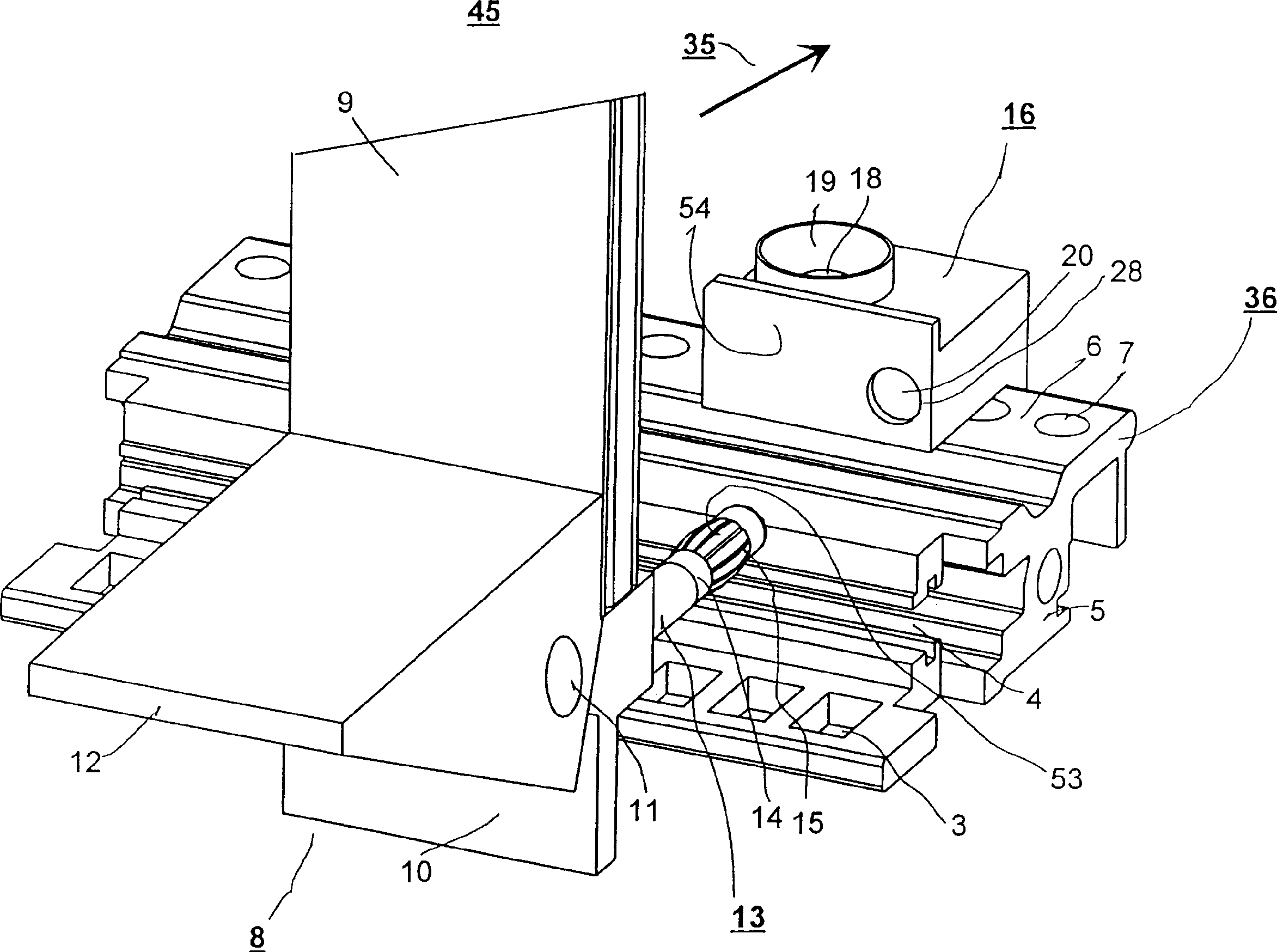
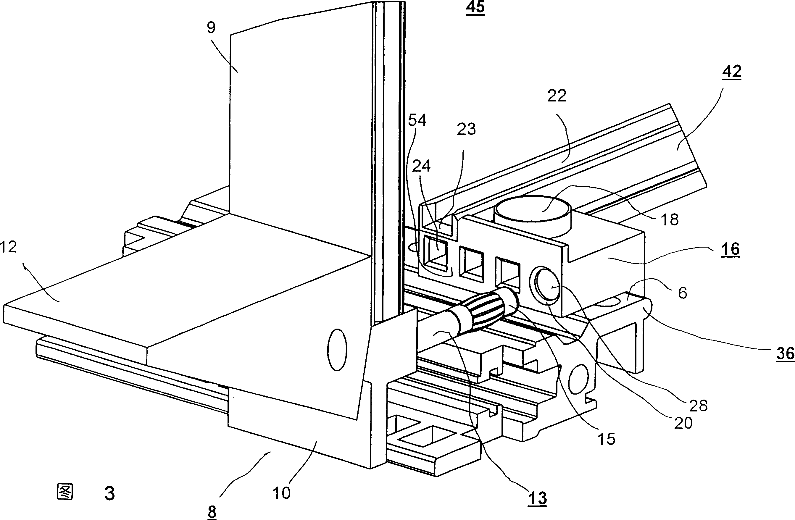
[0033] already described in part figure 1 In this case, the printed circuit insert 51 on the front side element 8 and the associated mounting position 45 has been provided according to the invention with insertable and extractable centering and contact elements 13 , 49 which face the insertion side 35 of the component frame 50 protrude. The centering and contact elements 13 , 49 are mounted, for example, respectively on a lower corner block 10 and an upper corner block 1 , wherein the corner blocks 10 , 1 are fastened to the front end of a front side panel 9 . These corner blocks are also used to hold a lower lever handle 12 and an upper lever handle 2 , with which the insertion and extraction of the unit consisting of the front element 8 and the printed circuit insert 51 is facilitated. The corner block with the centering and contact elements and the front side plate are made of electrically conductive material like the transverse connection rails.

[0034] Both the lower t...


PUM


Abstract

In a rack system for inserting electrical printed circuit board assemblies, front elements (52,8) for slots are provided with projecting plug-in and withdrawable centering and contact elements (13,49). These elements have associated receiving elements (16,21) composed of electrically conductive material and are mounted with low impedance to a transverse connecting rail. During an insertion process, the receiving elements and the centering and contact elements come into contact in a centered manner. When inserted, the receiving elements and the centering and contact elements provide a vibration-proof mechanical connection with a high adhesion force and a low-impedance contact with a high current carrying capacity.

Description

technical field [0001] The invention relates to a mounting system having a module frame having mounting locations for inserting electrical printed circuit cards. Background technique [0002] The component frame of such an assembly system provides volume elements for insertion of electrical printed circuit inserts. Such volume elements are also referred to as so-called mounting points and are usually arranged parallel to one another. Electrical printed circuit inserts, likewise arranged parallel to each other, are inserted therein. [0003] exist figure 1 A standard infrastructure of the component framework 50 is exemplarily shown in . The receiving cavity for the printed circuit insert is bounded by oppositely arranged transverse connecting rails made of electrically conductive material. exist figure 1 In the illustrated embodiment there are two lower transverse connecting rails 36 , 37 and two upper transverse connecting rails 38 , 39 opposite thereto. In this case, ...

Claims


Application Information

Patent Timeline
Patent Type & Authority Patents(China)
IPC IPC(8): H01R12/18H05K7/14
CPCH05K7/1455H05K7/1409H05K7/18
Inventor 西格弗里德·库勒库尔特-迈克尔·谢弗厄恩斯特·比伦斯坦
Owner RITTAL RES ELECTRONICS SYST GMBH & CO KG
Why Eureka
Try Eureka