
Construction site spraying device with surrounding spraying structure for environmental engineering

A technology of environmental engineering and spray device, which is applied in the directions of using liquid separating agent, dispersing particle separation, chemical instruments and methods, etc., can solve the problems of inconvenient movement and adjustment of angle, inconvenient adjustment of concentration of water mist, inconvenient adjustment of nozzle angle, etc. Achieve the effect of improving uniform stability and ensuring stability

Inactive Publication Date: 2021-06-22
合肥数喆信息科技有限公司
View PDF0 Cites 0 Cited by
  • Summary
  • Abstract
  • Description
  • Claims
  • Application Information

AI Technical Summary

Problems solved by technology

[0005] The purpose of the present invention is to provide a construction site spraying device for environmental engineering with a surrounding spray structure to solve the construction site spraying device in the prior art proposed in the above-mentioned background technology. When in use, the internal atomizing nozzle is not easy to move And adjusting the angle, it is not convenient for the atomizing nozzle of the spray device to supply water mist evenly to the inside of the main pipe, and it is affected by the inconvenience of adjusting the angle of the nozzle, which makes it inconvenient to adjust the concentrated amount of water mist in the unit space inside the main pipe, and the spray device It is difficult to adjust the outward diffusion range of water mist during use

Method used


Image

  • Construction site spraying device with surrounding spraying structure for environmental engineering
  • Construction site spraying device with surrounding spraying structure for environmental engineering
  • Construction site spraying device with surrounding spraying structure for environmental engineering

Examples


Embodiment Construction

[0033] The following will clearly and completely describe the technical solutions in the embodiments of the present invention with reference to the accompanying drawings in the embodiments of the present invention. Obviously, the described embodiments are only some, not all, embodiments of the present invention. Based on the embodiments of the present invention, all other embodiments obtained by persons of ordinary skill in the art without making creative efforts belong to the protection scope of the present invention.

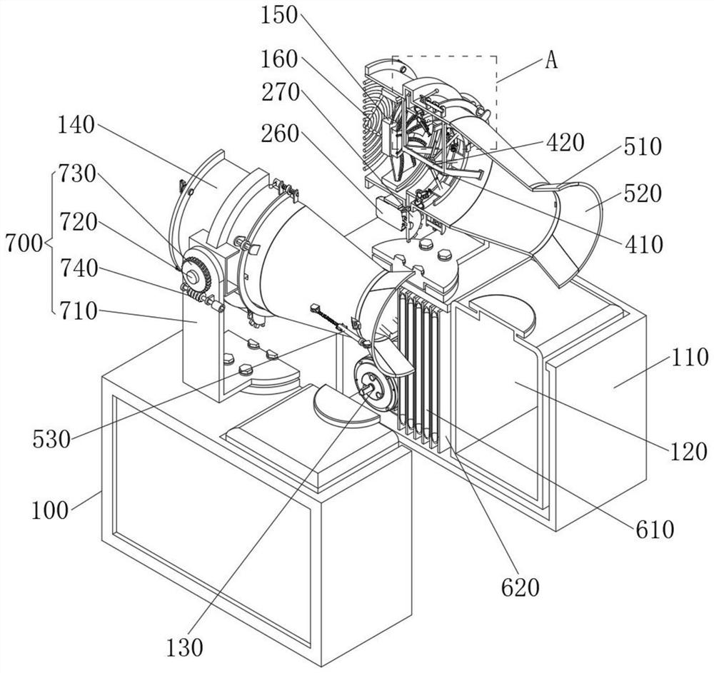
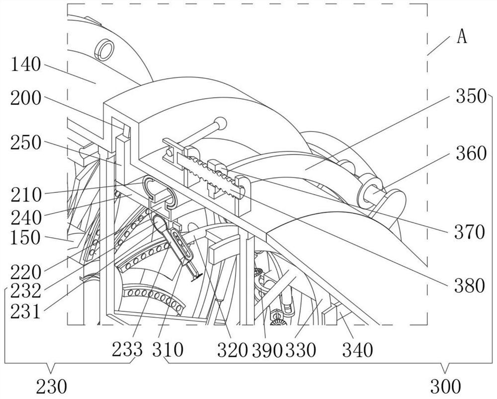
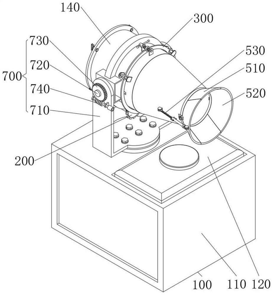
[0034] see Figure 1-10 , an embodiment provided by the present invention: a construction site spraying device for environmental engineering with a surrounding spray structure, including a sprayer main body 100, the sprayer main body 100 includes a base 110, and a storage tank is fixedly installed on the inner right side of the base 110 Water tank 120, a water pump 130 is fixedly installed on the inner left side of the base 110, and the input end of the water ...


PUM


Abstract

The invention relates to the technical field of spraying equipment, in particular to a construction site spraying device with a surrounding spraying structure for environmental engineering. The device comprises a spraying machine main body, wherein the spraying machine main body comprises a base, a water storage tank is fixedly mounted on the right side in the base, a water pump is fixedly mounted on the left side in the base, the input end of the water pump is communicated with the interior of the water storage tank, a gun barrel is arranged at the top of the base, and a draught fan is fixedly installed at the left end of the interior of the gun barrel. According to the invention, the fixed ring pipe and the inner ring pipe are connected in a sliding and rotating mode, spray head assemblies are evenly arranged on the inner wall of the inner ring pipe at equal intervals, and tooth meshing transmission between a gear ring and a gear is matched, so that when the device works, the inner ring pipe can be driven to continuously rotate in the fixed ring pipe by electrifying and starting a servo motor, the spray head assembly continuously and circularly rotates, the spray head assembly circularly and rotationally sprays mist into the gun barrel, and the uniformity and stability of water mist supply in the device are effectively improved.

Description

technical field [0001] The invention relates to the technical field of spray equipment, in particular to a construction site spray device for environmental engineering with a surrounding spray structure. Background technique [0002] Spray equipment is a kind of mechanical equipment that atomizes and sprays clean water. It is usually called a dust cannon. It is often used in construction sites with a lot of dust, such as dust reduction on the road surface and dust treatment in construction sites, to avoid environmental pollution. The high dust content in the construction site leads to a decline in the quality of the surrounding environment of the construction site; [0003] The dust suppression device in the prior art is generally used in combination with a fan and an atomizing nozzle. In actual use, the fan and the atomizing nozzle are fixed inside the main pipe of the spray device, and the fan is energized and rotated to drive The air flow surges, and the water mist spray...

Claims


Application Information

Patent Timeline
IPC IPC(8): B01D47/06
CPCB01D47/06
Inventor 夏文凯
Owner 合肥数喆信息科技有限公司
Learn More