
A light emitting diode testing device

A technology for light-emitting diodes and testing devices, which is applied in the directions of diode testing, measuring devices, measuring device casings, etc., can solve the problem of not being close to the real working environment of light-emitting diodes, and achieve the effect of high degree of automation, real working environment and high efficiency

Active Publication Date: 2021-07-30
江西省兆驰光电有限公司
View PDF21 Cites 0 Cited by
  • Summary
  • Abstract
  • Description
  • Claims
  • Application Information

AI Technical Summary

Problems solved by technology

[0002] In the production process of LED light sources, it is necessary to test the electrical and optical characteristics of the LED light source, such as measuring the LEDs on the adhesive film with a probe, and installing a photodetector under the LEDs to confirm the light emission Whether the diode can emit light normally or whether the light emitted meets the standard, so as to ensure the qualified rate of the product. Because the actual environment of the light-emitting diode in the actual use process is different, the requirements for the light emitted by it are also different. Existing The test device cannot be close to the real working environment of light-emitting diodes

Method used

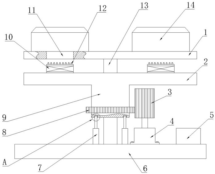
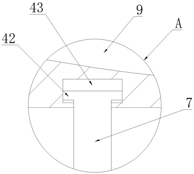
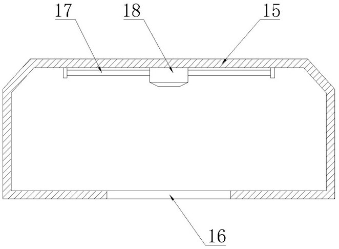

Image

  • A light emitting diode testing device
  • A light emitting diode testing device
  • A light emitting diode testing device

Examples


Embodiment Construction

[0032] The implementation of the present invention will be described in detail below with reference to the drawings and examples, so as to fully understand and implement the implementation process of how to use technical means to solve technical problems and achieve technical effects in the present invention.

[0033] In the description of the present invention, it should be noted that for orientation words, such as the term "center", "horizontal", "longitudinal", "length", "width", "thickness", "upper", "lower" , "Front", "Back", "Left", "Right", "Vertical", "Horizontal", "Top", "Bottom", "Inner", "Outer", "Clockwise", "Counterclockwise " and other indication orientations and positional relationships are based on the orientations or positional relationships shown in the drawings, and are only for the convenience of describing the present invention and simplifying the description, rather than indicating or implying that the device or element referred to must have a specific ori...


PUM


Abstract

The invention discloses a light-emitting diode testing device, comprising a test table, a first test room, a second test room, a third test room, a fourth test room, a light-emitting diode clamping component and a displacement component; a first test room The chamber includes a first housing and a first light sensor, the first light sensor is installed inside the first housing; the second test chamber includes a second housing, a second light sensor, a first transparent cover and a number of atomizers; the third test chamber includes a third housing and a third light sensor, the third light sensor is installed inside the third housing; the fourth test chamber includes a fourth housing, a fourth light sensor A detector, a water inlet pipe and a second transparent cover, the fourth light sensor and the water inlet pipe are installed inside the fourth casing, and the water inlet pipe is evenly distributed with a number of water diffusers; the light-emitting diode clamping assembly is used for clamping the light-emitting diode and Power up the LEDs. The working environment tested by the present invention is more real, and the test results are more accurate.

Description

technical field [0001] The invention relates to the technical field of light-emitting diode lighting, in particular to a light-emitting diode testing device. Background technique [0002] In the production process of LED light sources, it is necessary to test the electrical and optical characteristics of the LED light source, such as measuring the LEDs on the adhesive film with a probe, and installing a photodetector under the LEDs to confirm the light emission Whether the diode can emit light normally or whether the light emitted meets the standard, so as to ensure the qualified rate of the product. Because the actual environment of the light-emitting diode in the actual use process is different, the requirements for the light emitted by it are also different. Existing The test device cannot be close to the real working environment of light-emitting diodes. Contents of the invention [0003] The problem to be solved by the present invention is to provide a light-emitting...

Claims


Application Information

Patent Timeline
Patent Type & Authority Patents(China)
IPC IPC(8): G01R31/26G01R1/04G01M11/02
CPCG01M11/02G01R1/0408G01R1/0425G01R31/2635
Inventor 刘传标
Owner 江西省兆驰光电有限公司
Learn More