
Particle detection and removal method and equipment

A particle detection and removal technology, applied in the field of dust removal, can solve problems such as chip damage and achieve the effect of protecting products

Active Publication Date: 2021-06-18
JABIL CIRCUIT SINGAPOREPTE
View PDF5 Cites 0 Cited by
  • Summary
  • Abstract
  • Description
  • Claims
  • Application Information

AI Technical Summary

Problems solved by technology

[0003] The invention discloses a method and equipment for particle detection and removal to solve the problem that existing methods may cause damage to chips

Method used

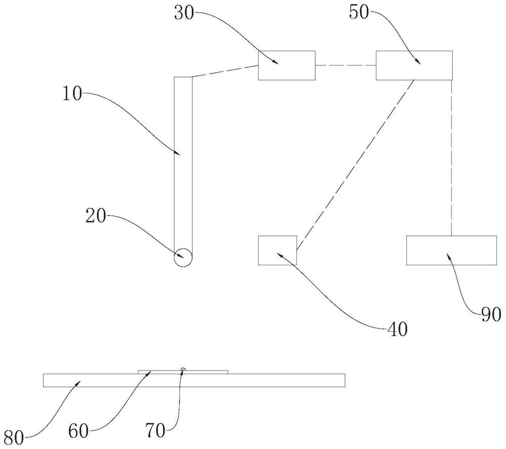
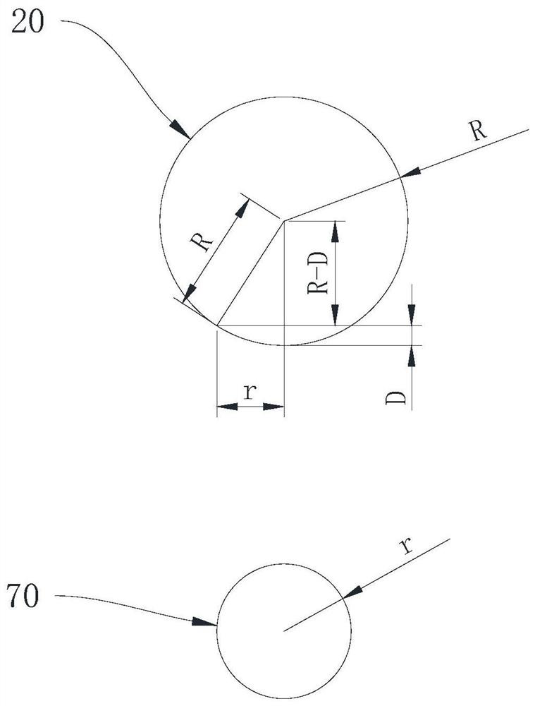

Image

  • Particle detection and removal method and equipment
  • Particle detection and removal method and equipment
  • Particle detection and removal method and equipment

Examples


Embodiment Construction

[0055] In order to make the purpose, technical solution and advantages of the present invention clearer, the technical solution of the present invention will be clearly and completely described below in conjunction with specific embodiments of the present invention and corresponding drawings. Apparently, the described embodiments are only some of the embodiments of the present invention, but not all of them. Based on the embodiments of the present invention, all other embodiments obtained by persons of ordinary skill in the art without making creative efforts belong to the protection scope of the present invention.

[0056] The technical solutions disclosed by various embodiments of the present invention will be described in detail below in conjunction with the accompanying drawings.

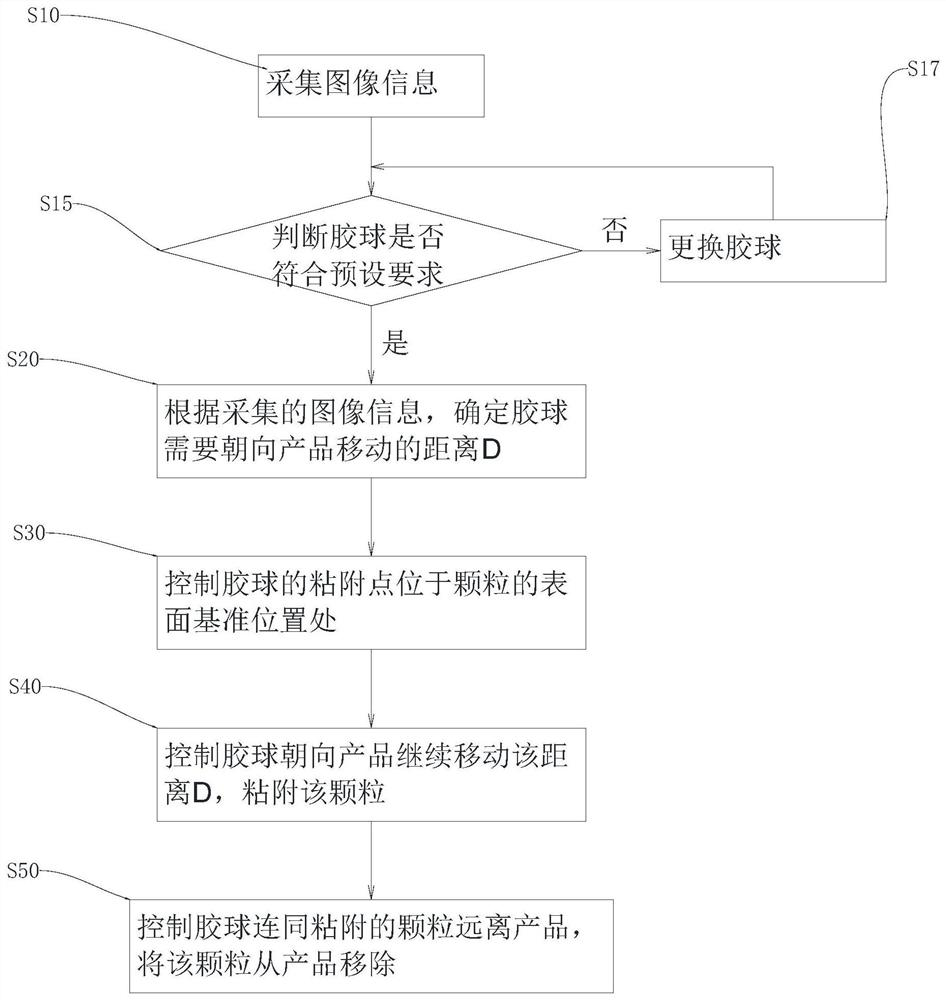
[0057] Such as figure 1 As shown, the present invention provides a method of particle 70 detection and removal, the method comprising:

[0058] S10, collecting image information, the image inf...


PUM


Abstract

The invention discloses a particle detection and removal method and equipment. The method comprises the steps of collecting image information which comprises the surface reference position of a particle on the surface of a product and the size of the particle on the surface of the product; according to the collected image information, determining the distance D of a rubber ball needing to move towards the product; controlling an adhesion point of the rubber ball to be located at a surface reference position of the particle; controlling the rubber ball to continuously move towards the product by the distance D, and adhering the particle to the rubber ball; and controlling the rubber ball and the adhered particle to be away from the product, and removing the particle from the product. By adopting the particle detection and removal method and equipment, the moving distance of the rubber ball towards the product can be accurately calculated when the particle is removed, so that the moving distance of the rubber ball is accurately controlled, the particle can be removed without causing great pressure to the product, and the product is effectively protected.

Description

technical field [0001] The invention relates to the field of dust removal, in particular to a particle detection and removal method and equipment. Background technique [0002] At present, the chip-on-board (COB) production line needs dust removal in the 2F clean room. The particles on the photosensitive area on the chip are removed by washing with deionized water. When washing with deionized water, the deionized water may cause damage to the chip. For damage, the particles can also be removed by adhesion technology, but when the adhesion medium used in the adhesion technology adheres to the particles, the force is too small to adhere to the particles, and too much force will cause impact on the chip. Contents of the invention [0003] The invention discloses a particle detection and removal method and equipment to solve the problem that the existing method may cause damage to the chip. [0004] In order to solve the above problems, the present invention adopts the follow...

Claims


Application Information

Patent Timeline
IPC IPC(8): G01B11/00G01N15/10G05D3/12H01L21/67H01L21/02
CPCG01B11/00G01N15/10G05D3/12H01L21/67011H01L21/02057G01N2015/1029
Inventor 吴秉陵
Owner JABIL CIRCUIT SINGAPOREPTE
Learn More