
Tubular Protection for Radiofrequency System to Improve the Recovery of Heavy Oils

a radiofrequency system and tubular protection technology, applied in the direction of dielectric heating, borehole/well accessories, anti-arctic heating, etc., can solve the problems of electrical insulation compromise and system deterioration, and achieve the effect of significant improving reliability

Active Publication Date: 2019-10-17
ENI SPA
View PDF0 Cites 1 Cited by
  • Summary
  • Abstract
  • Description
  • Claims
  • Application Information

AI Technical Summary

Benefits of technology

The invention is a system that prevents damage to its electrical components in aggressive environments. It does this by preventing contact with the fluid in the well, improving reliability. The system is especially useful for long antennas that may be exposed to higher risks over time. The system also uses a volumetric compensator to contain the expansion of heavy oil. Overall, the system provides better protection for its components in challenging environments.

Problems solved by technology

The use of RF for field applications using an antenna of considerable length gives rise to a serious problem of reliability over time if it is exposed to production fluids and heat and pressure cycles during operation of the well which can compromise the electrical insulation and thus give rise to deterioration of the system.

Method used


Image

  • Tubular Protection for Radiofrequency System to Improve the Recovery of Heavy Oils
  • Tubular Protection for Radiofrequency System to Improve the Recovery of Heavy Oils
  • Tubular Protection for Radiofrequency System to Improve the Recovery of Heavy Oils

Examples


Embodiment Construction

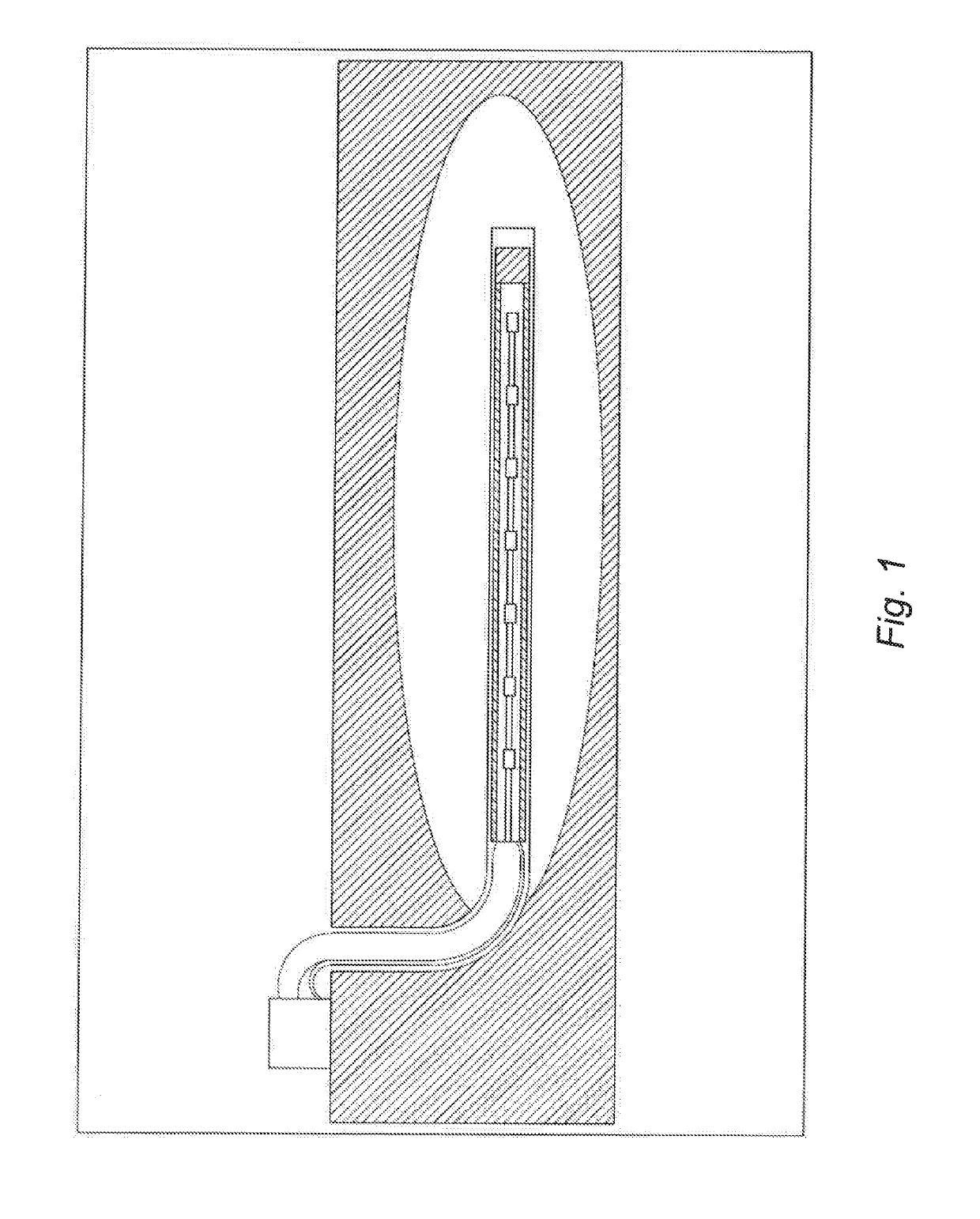
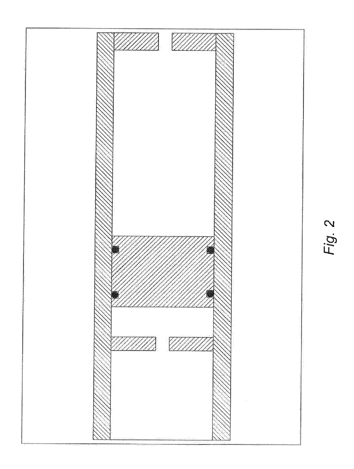
[0022]The system to which the present invention relates comprises a tube of material which is transparent to the RF emissions from the antenna, for example glass fibre, containing the antenna arranged axially. According to a preferred embodiment of the present invention a volumetric compensator is attached at its end. Other materials suitable for the tubular jacket may be materials which are transparent to electromagnetic waves and have mechanical properties enabling them to be installed in a well. The dielectric fluid (e.g. dielectric oil having a low thermal expansion coefficient) is exposed to a temperature rise when the antenna is in operation and as a consequence an increase in volume. For this reason this system is provided with a volumetric compensator capable of containing the volume of expanded oil, taking into account the dimensional constraints enabling it to be lowered down a well and operate in the production zone.

[0023]According to a preferred embodiment of the present...


PUM


Abstract

The present invention relates to a system for facilitating the extraction of hydrocarbons, in particular a tubular protection for an extraction system using the RF heating of highly viscous hydrocarbons in situ by means of an antenna having a coaxial array of mode converters.

Description

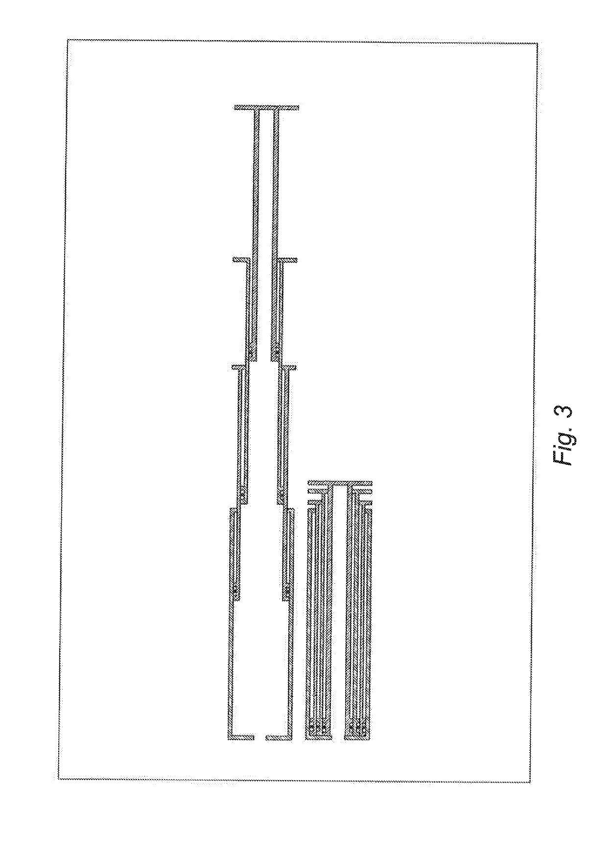
TECHNICAL FIELD[0001]The present invention relates to a system to aid extraction of hydrocarbons, in particular a tubular protection for an extraction system using RF heating of high-viscosity hydrocarbons in situ by means of an antenna comprising a coaxial array of mode converters.KNOWN ART[0002]International Patent Application WO2016 / 024197 by the same Applicant discloses a system comprising:[0003]a radiofrequency generator suitable for generating an electromagnetic signal; a coaxial transmission line connected to the generator and suitable for transmitting the signal along the drain, the coaxial line including an external conductor and an internal conductor which are separated by a layer of dielectric material;[0004]at least one mode converter which is positioned along the coaxial transmission line, in which the at least one mode converter interrupts the coaxial transmission line within the drain and comprises a first and a second conductor, the first conductor of the converter p...

Claims


Application Information

Patent Timeline
IPC IPC(8): E21B43/24E21B36/00E21B36/04H05B6/62H01Q13/20
CPCE21B36/003E21B36/006H01Q13/203H05B6/62E21B36/04E21B43/2401E21B36/00E21B43/24H05B2214/03
Inventor BURRAFATO, SEBASTIANOMALIARDI, ALBERTODI RENZO, DOMENICO
Owner ENI SPA
Learn More