
Integrated vector flash explosion soot blower

A soot blowing device and flash explosion technology, which is applied in the fields of solid residue removal, combustion product treatment, and combustion methods, and can solve problems such as equipment blowout, shutdown, and leakage

Pending Publication Date: 2021-06-18
胡建廷
View PDF0 Cites 0 Cited by
  • Summary
  • Abstract
  • Description
  • Claims
  • Application Information

AI Technical Summary

Problems solved by technology

[0002] The soot blowing devices currently on the market or have been installed in a large number of boiler tail flues generally use steam continuous soot blowing devices, sonic wave soot blowing devices, and shock wave soot blowing devices. Steam, due to the low working parameters, is easy to condense and stick to ash, which will lead to a large increase in smoke exhaust and heat loss of the boiler. At the same time, when the mechanical failure of the purging equipment itself occurs, if it is not discovered in time, it is easy to blow out the equipment. , causing leakage and causing shutdown of the furnace; the sound wave soot blowing device uses low-pressure compressed air to generate mechanical vibration energy, which resonates with the floating ash. Due to the low pressure, the soot blowing effect is unsatisfactory, but it is helpless for viscous dust; the shock wave The soot blower adopts the pressure wave generated by the deflagration of combustible gas. The pressure can reach up to 0.1MPa, and the soot blowing effect can meet the expectations. However, the working parameters of the medium are low, and the deflagration occurs outside the pulse tank. The working characteristics determine that its operating area is too small. The soot blowing blind area is too large, and it is easy to squib, resulting in too much equipment installation, which requires a considerable number of soot blowers and consumes a lot of flammable and explosive gases, usually hydrogen, acetylene, methane, gas, liquefied petroleum gas etc. At the same time, these bottled combustible gases are stored near the boiler for a long time, which is really a great safety hazard. Therefore, it is necessary to carry out technical upgrading or product replacement
[0003] The two fundamental problems to be solved by the soot blowing device are: one is the quality of the blowing medium; the other is the problem of rapid detonation

Method used


Image

  • Integrated vector flash explosion soot blower
  • Integrated vector flash explosion soot blower

Examples


Embodiment Construction

[0007] The present invention is described in further detail below with reference to accompanying drawing:

[0008] Process principle of the present invention and structural principle are described as follows:

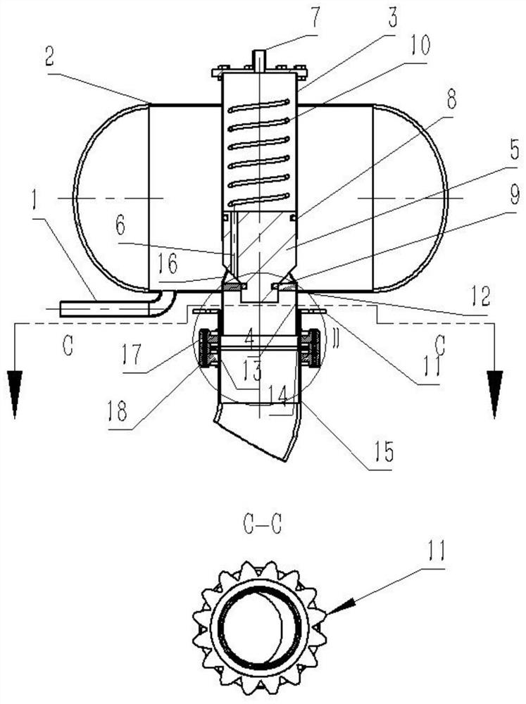
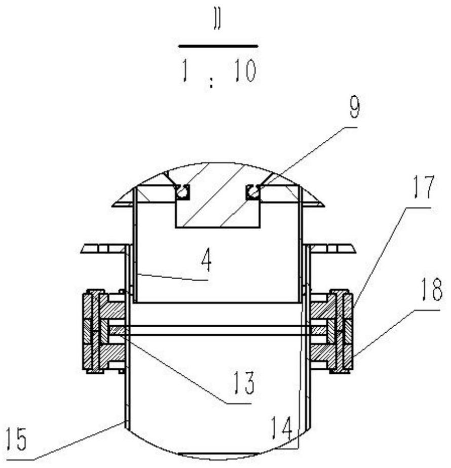
[0009] Refer to attached figure 1 , attached figure 2 As shown, the integrated vector flash detonation soot blowing device includes: a flasher and a nozzle, wherein the key component in the flasher is a flash valve; wherein the key component in the nozzle is the vector nozzle 15.

[0010] The flasher is composed of an inlet pipe 1, a flash tank 2, a flash valve and the like.

[0011] Compressed air is selected as the flash explosion medium in this embodiment. The compressed air is very safe and easy to obtain. The compressed air first enters the inlet pipe 1, and then is introduced into the flash explosion tank 2.

[0012] Described flasher is made up of flasher tank 2 and flasher valve.

[0013] And the working principle of the flash valve of the integrated vecto...


PUM


Abstract

The invention relates to a boiler soot blowing device, in particular to an integrated vector flash explosion soot blowing device which is widely used in the operation process of a power station boiler and a garbage incinerator and mainly comprises a flash explosion device and a spray pipe, the main technical characteristics are that the spray pipe can maintain dynamic rotation, the outlet jet flow of the spray pipe and the axis of the spray pipe form an included angle, the spray pipe is tightly close to the outlet of a flash explosion tank, jet flow energy loss is reduced, the soot blowing effect is improved, and compressed air energy consumption is reduced.

Description

technical field [0001] The invention relates to a boiler flue soot blowing device, in particular to an integrated vector flash explosion soot blowing device widely used in the operation process of boilers of various levels and types, especially power plant boilers and waste heat boilers. Background technique [0002] The soot blowing devices currently on the market or which have been installed in a large number of boiler tail flues generally use steam continuous soot blowing devices, sonic wave soot blowing devices, and shock wave soot blowing devices. Steam, due to the low working parameters, is easy to condense and stick to ash, which will lead to a large increase in smoke exhaust and heat loss of the boiler. At the same time, when the mechanical failure of the purging equipment itself occurs, if it is not found in time, it is easy to blow out the equipment. , causing leakage and shutdown of the furnace; the sonic soot blowing device uses low-pressure compressed air to gen...

Claims


Application Information

Patent Timeline
IPC IPC(8): F23J3/02
CPCF23J3/02
Inventor 胡建廷
Owner 胡建廷
Learn More