
Tyre

A technology for tires and treads, which is applied to tire parts, tire treads/tread patterns, vehicle components, etc., and can solve problems such as inability to fully exert the wiping effect, low ground pressure, and inability to fully improve braking performance. Achieve the effects of improving the wiping effect, increasing the ground pressure, and reducing the contact angle

Pending Publication Date: 2021-06-18
SUMITOMO RUBBER IND LTD
View PDF1 Cites 0 Cited by
  • Summary
  • Abstract
  • Description
  • Claims
  • Application Information

AI Technical Summary

Problems solved by technology

However, in this proposal, the ground pressure at the contact portion between the wall surface and the icy road surface will be lower instead.
Therefore, similar to the case where the contact angle is large, the wiping effect cannot be fully exerted, and the braking performance cannot be sufficiently improved.

Method used


Image

  • Tyre
  • Tyre
  • Tyre

Examples


Embodiment

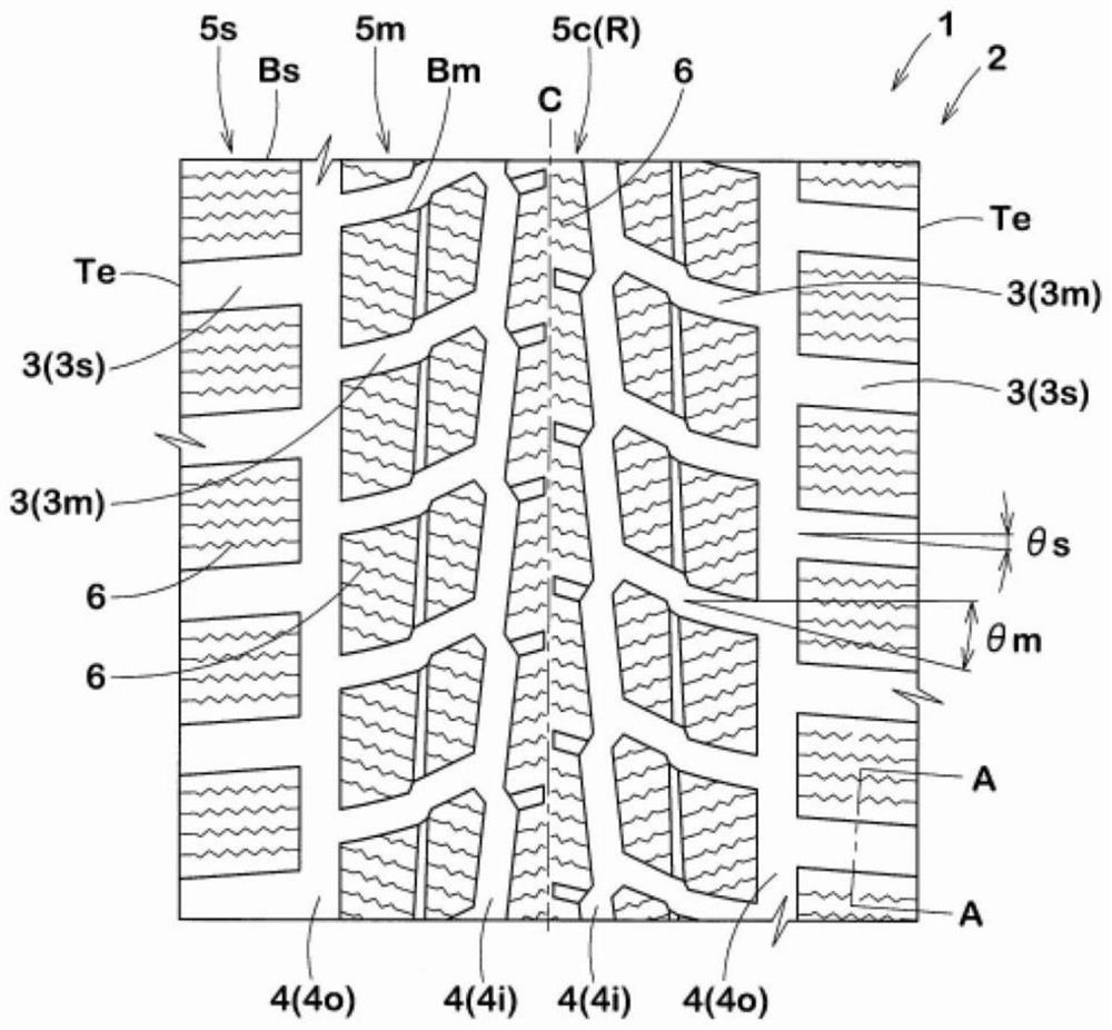
[0081] Prototype based on the specifications in Table 1 to figure 1 A studless tire of size 195 / 65R15 with the tread pattern shown as the basic pattern was tested for braking performance on icy roads when it was new and when it was 50% worn.

[0082] In Comparative Example 1, the wall surface of the lateral groove was formed with a slope inclined in a direction in which the groove width decreases as it goes toward the bottom of the groove. The angle of the wall with respect to the normal to the tread surface is 10 degrees. In Comparative Example 2, the wall surfaces of the lateral grooves were formed with slopes inclined in such a direction that the groove width increases toward the bottom of the groove. The angle of the wall with respect to the normal to the tread surface is 7 degrees. In the embodiment, serrations are formed on the wall surfaces of the middle lateral groove and the shoulder lateral groove. Furthermore, in Example 4, the angle θc becomes larger as the firs...


PUM


Abstract

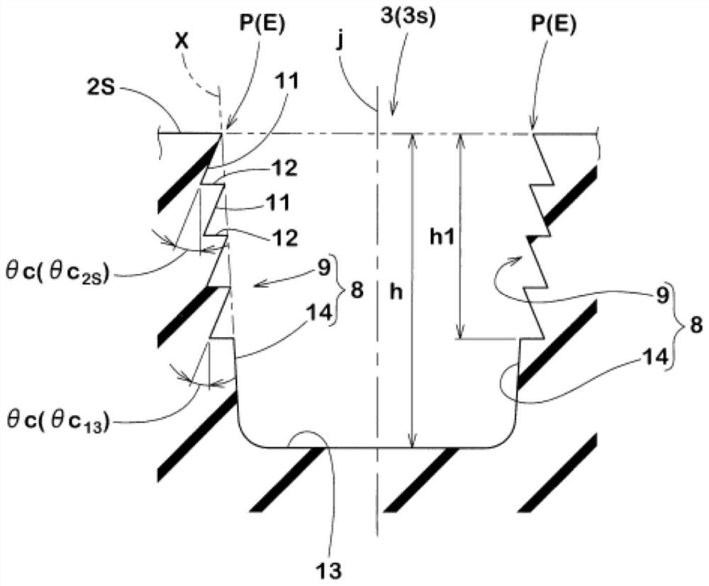
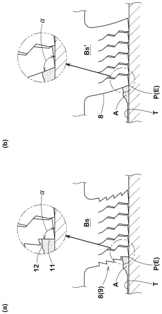
The invention improves wiping effect and improves braking performance on icy roads. In a cross section at right angles to the longitudinal direction of a lateral groove (3), at least one wall surface (8) of the lateral groove (3) includes a serrated part (9). The serrated part (9) is formed by alternately repeating multiple first face parts (11) and second face parts (12), The first face parts (11) tilt in a direction in which groove width becomes wider to the groove bottom (13), The second face parts (12) extend substantially parallel to the tread surface (2S) from the groove bottom side end (11e) to the groove width center (j) side.

Description

technical field [0001] The present invention is suitable as a studless tire, and particularly relates to a tire with improved braking performance on icy roads. Background technique [0002] For studless tires, in order to improve running performance on icy and snowy roads, etc., a pattern in which blocks defined by circumferential grooves and lateral grooves are arranged on the tread portion is widely used. [0003] The wall surface of the lateral groove used in such a pattern is generally formed with an inclined surface inclined in a direction in which the groove width decreases toward the bottom of the groove (see, for example, Patent Document 1 below). [0004] Patent Document 1: Japanese Patent Application Laid-Open No. 11-99810 [0005] On the other hand, on an icy road surface, a thin water film is formed by melting the ice due to the contact pressure of the tire. And, if this water film is sandwiched between the tread surface and the icy road surface, the grip force...

Claims


Application Information

Patent Timeline
IPC IPC(8): B60C11/13B60C11/03
CPCB60C11/1307B60C11/03B60C2011/0358B60C11/24B60C11/0332B60C11/042B60C11/11B60C2011/0374B60C2011/1213
Inventor 中岛幸一
Owner SUMITOMO RUBBER IND LTD
Learn More