
Drilling clamp for multi-spindle drilling machine

A technology for drilling jigs and multi-axis drilling machines, which is applied in the directions of boring/drilling, drilling/drilling equipment, parts of boring machines/drilling machines, etc. Hole position and other issues to achieve the effect of improving processing efficiency and fast clamping and fixing

Active Publication Date: 2021-06-18
杭州佳克威机械制造有限公司
View PDF21 Cites 4 Cited by
  • Summary
  • Abstract
  • Description
  • Claims
  • Application Information

AI Technical Summary

Problems solved by technology

[0005] Aiming at the deficiencies of the prior art, the present invention provides a drilling jig for a multi-axis drilling machine, which solves the problem that the workpiece cannot be clamped quickly and cannot be automatically adjusted when drilling the side surface wall of some ring disc parts. The punching position needs to be manually adjusted by workers, which reduces the processing efficiency, and it is necessary to replace different fixtures when clamping parts with different diameters, which is time-consuming and labor-intensive, which affects the processing efficiency.

Method used


Image

  • Drilling clamp for multi-spindle drilling machine
  • Drilling clamp for multi-spindle drilling machine
  • Drilling clamp for multi-spindle drilling machine

Examples


Embodiment Construction

[0027] The following will clearly and completely describe the technical solutions in the embodiments of the present invention with reference to the accompanying drawings in the embodiments of the present invention. Obviously, the described embodiments are only some, not all, embodiments of the present invention. Based on the embodiments of the present invention, all other embodiments obtained by persons of ordinary skill in the art without making creative efforts belong to the protection scope of the present invention.

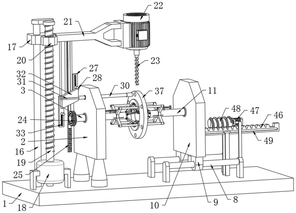
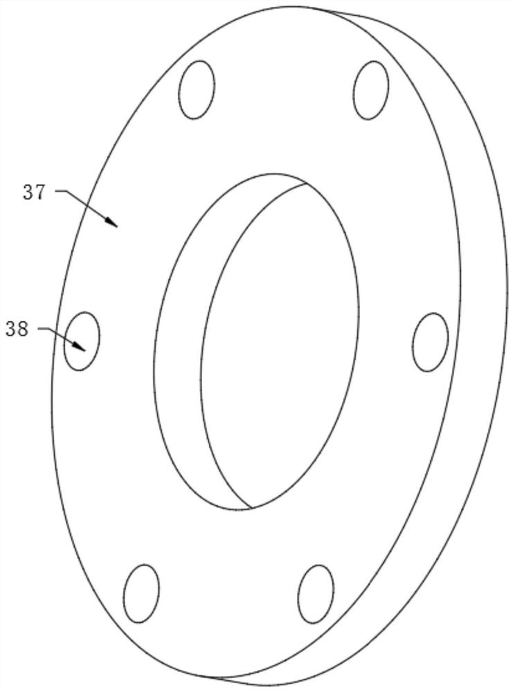
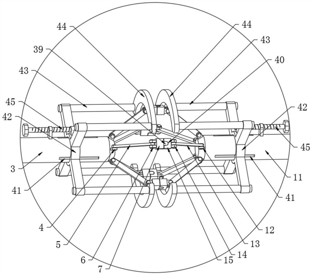
[0028] see Figure 1-7, the present invention provides a technical solution: a drilling jig for a multi-axis drilling machine, including a base 1, the left part of the upper end surface of the base 1 is fixedly connected with a first support plate 2 through a leg, and the right end surface of the first support plate 2 runs through and rotates Connected with the first rotating shaft 3, the right part of the outer wall of the first rotating shaft 3 is connected ...


PUM


Abstract

The invention discloses a drilling clamp for a multi-spindle drilling machine, and relates to the technical field of multi-spindle drilling machine clamps. The drilling clamp for the multi-spindle drilling machine comprises a base, a first supporting plate is fixedly connected to the left portion of the upper end face of the base through supporting legs, a first rotating shaft is rotatably connected to the right end face of the first supporting plate in a penetrating mode, first supporting rods are rotatably connected to the right portion of the outer surface wall of the first rotating shaft at equal intervals through the circumference of first convex lugs, the left portion of the upper end face of the base is fixedly connected with a first driving motor through a fixing frame, the first driving motor is coaxially and fixedly connected with a lead screw through an output shaft, the exterior of the lead screw is in threaded connection with a threaded sleeve block, the rear end face of the threaded sleeve block is fixedly connected to the front end face of a supporting table, and the right end face of the supporting table is fixedly connected with a Y-shaped plate. According to the drilling clamp, circular ring disc parts with different diameter sizes can be rapidly positioned and clamped, time and labor are saved, the machining efficiency is improved, the outer side walls of the circular ring disc parts can be drilled, the drilling positions can be automatically adjusted, and the machining efficiency is improved.

Description

technical field [0001] The invention relates to the technical field of clamps for multi-axis drilling machines, in particular to a drilling clamp for multi-axis drilling machines. Background technique [0002] Multi-axis drilling machine, commonly known as multi-axis device, multi-hole drill or multi-axis drilling machine, is a kind of machine tool equipment used in drilling and tapping in the mechanical field. The drilling machine with vertical spindle and fixed center position is called vertical drill for short. Vertical drills with multiple drilling axes, called multi-axis drilling machines, are often used in machinery manufacturing and repair factories to process holes in small workpieces. At present, fixtures are widely used in the process of various industries in machinery manufacturing to fix processing objects. , A process equipment that enables it to occupy the correct position and accept construction. [0003] But at present existing multi-axis drilling machine dr...

Claims


Application Information

Patent Timeline
IPC IPC(8): B23Q3/00B23Q7/00B23B47/20B23B39/00
CPCB23Q3/00B23Q7/00B23Q5/40B23B39/00
Inventor 沈飞
Owner 杭州佳克威机械制造有限公司
Learn More