
Three-dimensional laser head for CO2 nonmetal laser cutting

A laser cutting and three-dimensional laser technology, applied in welding/cutting auxiliary equipment, welding/welding/cutting items, laser welding equipment, etc., can solve the problems that the laser head cannot meet the working requirements, and it is difficult to meet the processing requirements of composite material components, etc. Achieve the effect of expanding the range of processing capacity, reducing the weight of the mechanism, and improving the transmission accuracy

Pending Publication Date: 2021-06-18
NOBOT INTELLIGENT EQUIP (SHANDONG) CO LTD
View PDF5 Cites 0 Cited by
  • Summary
  • Abstract
  • Description
  • Claims
  • Application Information

AI Technical Summary

Problems solved by technology

[0002] In recent years, composite materials have been widely used in aviation, aerospace, shipbuilding, high-speed rail, automobile and other industrial fields due to their excellent performance; composite materials usually have the characteristics of high hardness, high strength, poor thermal conductivity, anisotropy and discreteness, etc. As the structural complexity and processing precision of components are getting higher and higher, traditional processing methods are becoming more and more difficult to meet the processing requirements of composite material components; 3D CO 2 Laser cutting machine can realize efficient and high-precision processing of complex structural components of composite materials, and is an inevitable choice to meet the processing requirements of such components at present
[0003] The laser cutting head is a three-dimensional CO 2 The key component of laser cutting machine, 3D CO 2 The laser cutting machine has specific requirements for its structure, such as rotation angle, processing temperature, weight, etc. when working, all kinds of three-dimensional fiber laser heads and planar CO 2 None of the laser heads can meet their working requirements

Method used


Image

  • Three-dimensional laser head for CO2 nonmetal laser cutting
  • Three-dimensional laser head for CO2 nonmetal laser cutting
  • Three-dimensional laser head for CO2 nonmetal laser cutting

Examples


Embodiment Construction

[0025] The technical solutions of the present invention will be further explained below through specific embodiments.

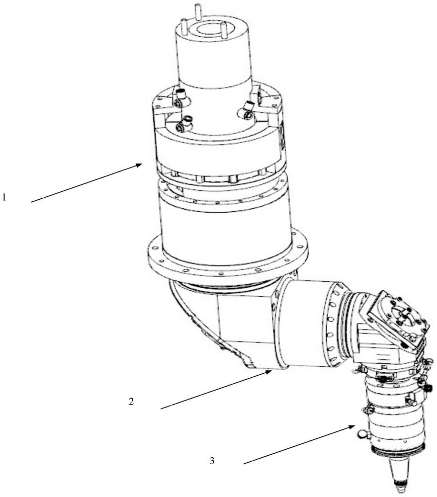
[0026] Referring to the accompanying drawings, the present invention provides a CO 2 The three-dimensional laser head for non-metallic laser cutting is characterized in that it includes a C-axis rotation assembly 1, a B-axis swing assembly 2 and a laser head 3, the B-axis swing assembly is installed on the shaft of the C-axis rotation assembly, and the laser head 3 is installed on the swing shaft of the B-axis swing assembly 2.

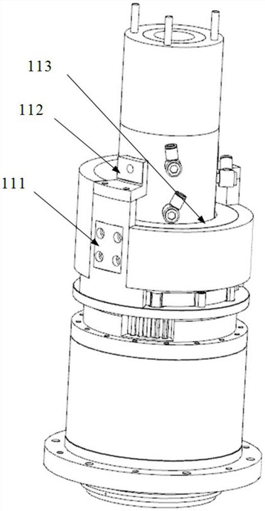
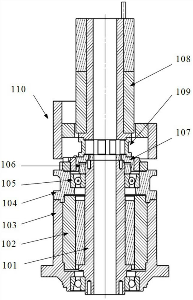
[0027] The C-axis rotating assembly 1 includes a rotating shaft 101, a C-axis motor 102, a C-axis encoder 107, and a gas-electric-hydraulic conductive slip ring 108; the rotor of the C-axis motor 102 is set on the rotating shaft 101 through screws, and the stator is set on the outer frame of the C-axis motor The inner side of 103; the outer side of the C-axis motor frame 103 is provided with a connecting flange matching the end of t...


PUM


Abstract

The invention provides a three-dimensional laser head for CO2 nonmetal laser cutting. The three-dimensional laser head is characterized by comprising a C-axis rotating assembly, a B-axis swinging assembly and a laser head body, the B-axis swinging assembly is installed on a rotating shaft of the C-axis rotating assembly, and the laser head body is installed on a swinging shaft of the B-axis swinging assembly. The C-axis rotating assembly can rotate by n*360 degrees, the B-axis swinging assembly is installed on the rotating shaft of the C-axis rotating assembly and can swing by + / -135 degrees, and it is guaranteed that laser beams in the B-axis swinging assembly can be accurately reflected all the time in the movement process and are stably output through a focusing lens of the laser head body; and the processing capacity range of a three-dimensional laser cutting machine is expanded.

Description

technical field [0001] The invention belongs to the technical field of laser cutting, and belongs to a three-dimensional CO for non-metallic laser cutting. 2 laser head. Background technique [0002] In recent years, composite materials have been widely used in aviation, aerospace, shipbuilding, high-speed rail, automobile and other industrial fields due to their excellent performance; composite materials usually have the characteristics of high hardness, high strength, poor thermal conductivity, anisotropy and discreteness, etc. As the structural complexity and processing precision of components are getting higher and higher, traditional processing methods are becoming more and more difficult to meet the processing requirements of composite material components; 3D CO 2 Laser cutting machine can realize efficient and high-precision processing of complex structural components of composite materials, and is an inevitable choice to meet the processing requirements of such comp...

Claims


Application Information

Patent Timeline
Patent Type & Authority Applications(China)
IPC IPC(8): B23K26/38B23K26/402B23K26/08B23K26/064B23K26/70
CPCB23K26/38B23K26/402B23K26/0884B23K26/0643B23K26/703B23K37/003B23K2103/30B23K2103/50
Inventor 闫新华赵贞奎付黎伟吴建超孙群赵栋杰
Owner NOBOT INTELLIGENT EQUIP (SHANDONG) CO LTD
Learn More