Solar sludge drying device
A technology of drying sludge and solar energy, applied in sludge treatment, water/sludge/sewage treatment, water/sewage treatment, etc., can solve the problem of unsatisfactory light collection effect on the back side, and improve light coverage And real-time dynamic coverage accuracy, shorten the standby time, increase the effect of utilization
- Summary
- Abstract
- Description
- Claims
- Application Information
AI Technical Summary
Problems solved by technology
Method used
Image
Examples
specific Embodiment 1
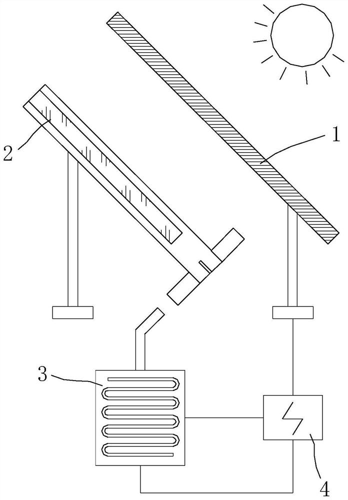
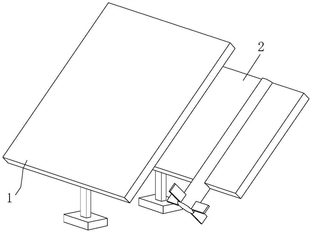
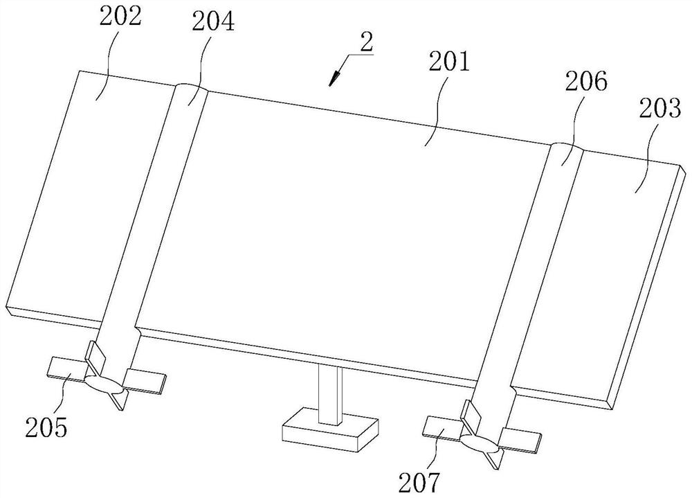
[0040] Specific embodiment one: please refer to Figure 1-7 A solar sludge drying device includes a photovoltaic panel 1 , a storage battery 4 , a heating unit 3 and a reflection unit 2 .
[0041]Both the sunny side and the back side of the photovoltaic panel 1 are effective equipment sides, that is, the photovoltaic effect can be generated on both the sun side and the back side to charge the battery 4 . The backside of the photovoltaic panel 1 is divided into a first light area 101 and a second light area 102 . The light radiation received by the first light area 101 comes from the direct reflection of the second reflector 202 or the sunlight re-reflected by the first reflector 201 . The light radiation received by the second light area 102 comes from the direct reflection of the third reflector 203 or the sunlight re-reflected by the first reflector 201 .
[0042] The reflection unit 2 is located on the backside of the photovoltaic panel 1 , and the reflection unit 2 makes...
specific Embodiment 2
[0049] Specific embodiment 2: On the basis of specific embodiment 1, please refer to a solar drying sludge device in 8-12, and the left and right edges of the first light area 101 and the second light area 102 are equipped with light partitions 103 . The optical partitions 103 are electrically connected to the controller 5 .
[0050] After the light division 103 of the first light zone 101 is irradiated by sunlight, the controller 5 controls the electromagnetic valve 306 of the heating group 301 to open, so that the heated gas in the box body 303 is ejected. After the gas is ejected, it acts on the fan one blade 205, and the fan The first leaf 205 drives the first rotating shaft 204 to rotate, so that the second reflective plate 202 is angled relative to the photovoltaic panel 1 , so that the reflected light is always located in the first light area 101 .
[0051] After the optical division 103 of the second optical area 102 is irradiated by sunlight, the controller 5 controls...
specific Embodiment 3
[0055] Specific embodiment three: On the basis of specific embodiment two, the number of air pipes 304 for heating a group 301 is two, which are divided into daytime air pipes and night air pipes. Daytime weather pipe and night trachea jet port are opposite to fan one blade 205 positions, after daytime weather pipe blows air, fan one blade 205 rotates clockwise to the west, and after night air pipe sprays, fan one blade 205 turns eastward counterclockwise. There are two solenoid valves 306, which are divided into a daytime valve and a nighttime valve, and the daytime valve and the nighttime valve correspond to the daytime air pipe and the night air pipe respectively. The day valve is located in the day tube. The night valve is located in the night trachea. Both the daytime valve and the nighttime valve are electrically connected to the controller 5 . The heating group 301 and the heating group 302 are components with the same structure.
[0056] When the sun shines on the r...
PUM
 Abstract
Description
Claims
Application Information
 - R&D
- Intellectual Property
- Life Sciences
- Materials
- Tech Scout
- Unparalleled Data Quality
- Higher Quality Content
- 60% Fewer Hallucinations
Browse by: Latest US Patents, China's latest patents, Technical Efficacy Thesaurus, Application Domain, Technology Topic, Popular Technical Reports.
© 2025 PatSnap. All rights reserved.Legal|Privacy policy|Modern Slavery Act Transparency Statement|Sitemap|About US| Contact US: help@patsnap.com


