Numerical control laser cutting machine

A digitally controlled laser and cutting machine technology, applied in laser welding equipment, welding equipment, metal processing equipment, etc., can solve the problems of reduced cutting efficiency and cutting quality, inconvenience of being limited and fixed by cutting parts, inconvenient loading and unloading of cutting parts, etc. , to achieve the effect of convenient electric adjustment operation, avoiding the reduction of cutting efficiency and cutting quality, and simple structure

Inactive Publication Date: 2021-06-18
广州市景让信息科技有限公司
View PDF0 Cites 6 Cited by
  • Summary
  • Abstract
  • Description
  • Claims
  • Application Information

AI Technical Summary

Problems solved by technology

[0004] The object of the present invention is to provide a numerically controlled laser cutting machine, which solves the inconvenience of loading and unloading the cut piece during use of the numerically controlled laser cutting machine currently on the market, and it is inconvenient to limit and fix the cut piece, and the cutting head The height adjustment of the distance from the object to be cut remains unchanged, which will easily lead to a decrease in cutting efficiency and cutting quality or burn out the cutting nozzle. In addition, the existing CNC laser cutting machine also has the problems of inconvenient movement adjustment and poor cutting accuracy.

Method used


Image

  • Numerical control laser cutting machine
  • Numerical control laser cutting machine
  • Numerical control laser cutting machine

Examples


Embodiment Construction

[0026] The following will clearly and completely describe the technical solutions in the embodiments of the present invention with reference to the accompanying drawings in the embodiments of the present invention. Obviously, the described embodiments are only some, not all, embodiments of the present invention. Based on the embodiments of the present invention, all other embodiments obtained by persons of ordinary skill in the art without making creative efforts belong to the protection scope of the present invention.

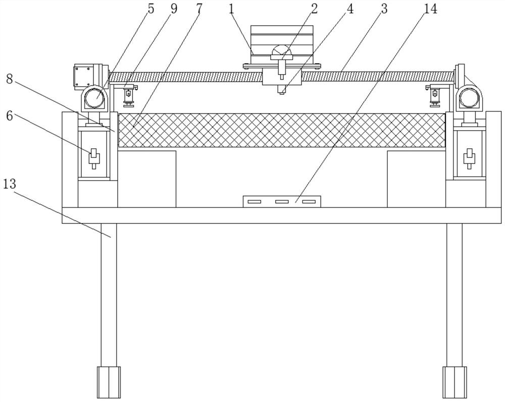
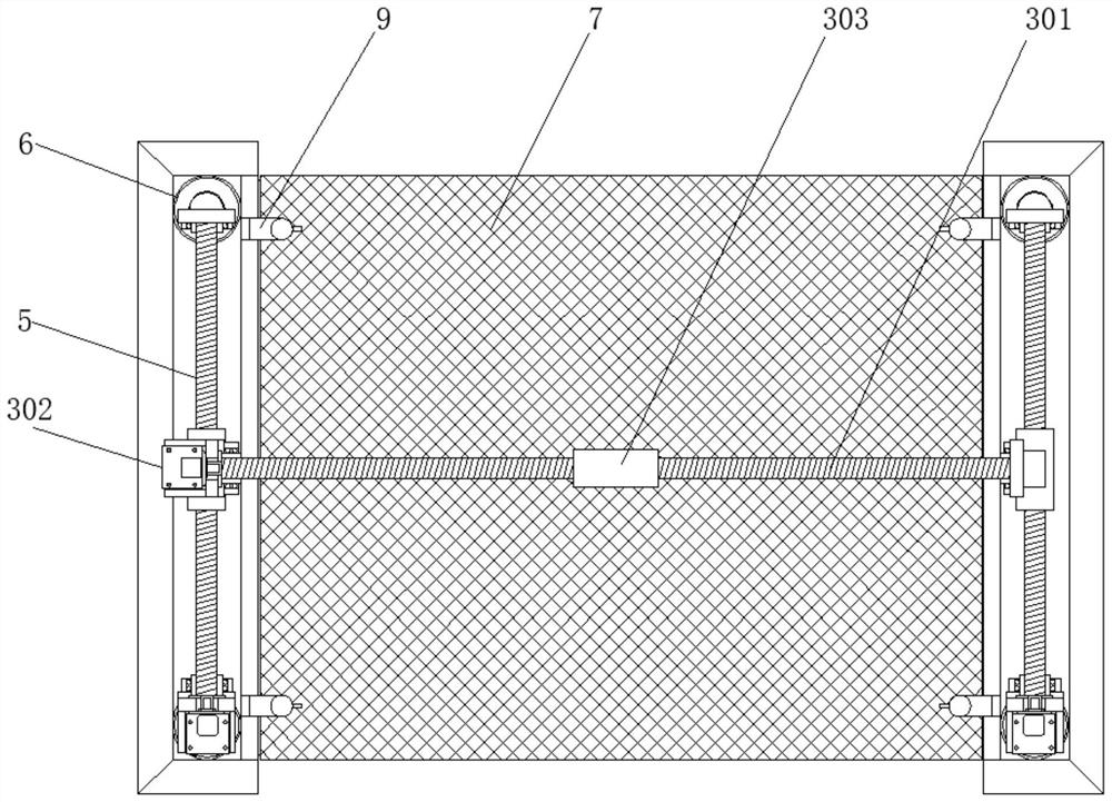
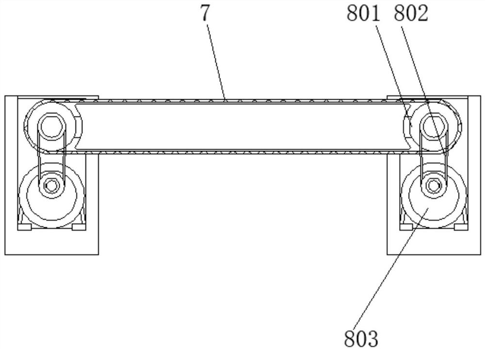
[0027] see Figure 1-5 , a numerically controlled laser cutting machine, comprising a numerically controlled laser cutting machine main body 1, a laser cutting head 2, an X-axis moving mechanism 3, a lead screw 301, a servo motor 302, a ball nut 303, a distance measuring sensor 4, a Y-axis moving mechanism 5, First lifting mechanism 6, cutting guide table 7, driving mechanism 8, rotating roller 801, V-belt 802, stepping motor 803, bracket 9, second lifting mec...


PUM


Abstract

The invention discloses a numerical control laser cutting machine which comprises a numerical control laser cutting machine body, a cutting guide table and a fixing mechanism. A laser cutting head is installed on the front side face of the numerical control laser cutting machine body, and an X-axis moving mechanism is installed below the numerical control laser cutting machine body. A distance measuring sensor is installed below the middle position of the X-axis moving mechanism, Y-axis moving mechanisms are arranged below the left end and the right end of the X-axis moving mechanism, first lifting mechanisms are installed below the front end and the rear end of each Y-axis moving mechanism, and driving mechanisms are arranged on the inner sides of the first lifting mechanisms. The cutting guide table is installed between the adjacent inner sides of the driving mechanisms, supports are installed on the upper edges of the driving mechanisms, and fixing mechanisms are installed at the lower ends of second lifting mechanisms. According to the numerical control laser cutting machine, a cut object is automatically fed and discharged through the rotation effect of the cutting guide table, operation is more convenient and faster, the burden of workers can be better relieved, and the automation degree is higher.

Description

technical field [0001] The invention relates to the technical field of cutting devices, in particular to a numerically controlled laser cutting machine. Background technique [0002] The CNC cutting machine has the characteristics of fast cutting speed and small cutting seam during the cutting process. The design of the industrial master machine tool ensures the high speed and stability of the laser cutting process. Fiber lasers with different powers are selected, which can cut and punch various metals and materials at high speed and precision. , always able to maintain the same cutting quality. Laser machines are used in sheet metal processing, environmental protection equipment, chassis electric cabinets, agricultural machinery, kitchen utensils and bathrooms, auto parts, sports equipment, lighting fixtures, metal crafts, fans, electrical parts, communication equipment, food machinery, logistics equipment, advertising, hardware, Windows and other industries. [0003] Ho...

Claims


Application Information

Patent Timeline
Patent Type & Authority Applications(China)
IPC IPC(8): B23K26/38B23K26/70
CPCB23K26/38B23K26/70B23K26/702
Inventor 陈觉
Owner 广州市景让信息科技有限公司
Why Eureka
Try Eureka