Left atrial appendage occluder and suturing method

An occluder and suture hole technology, applied in medical science, surgery, ligation, etc., can solve the problems of difficult readjustment and unsatisfactory release of the occluder.

Active Publication Date: 2021-06-18
LIFETECH SCIENTIFIC (SHENZHEN) CO LTD
View PDF4 Cites 0 Cited by
  • Summary
  • Abstract
  • Description
  • Claims
  • Application Information

AI Technical Summary

Problems solved by technology

[0006] The purpose of the present invention is to provide a fixing method for a fixed disk, an occluder and a film body, so as...

Method used


Image

  • Left atrial appendage occluder and suturing method
  • Left atrial appendage occluder and suturing method
  • Left atrial appendage occluder and suturing method

Examples


Embodiment 1

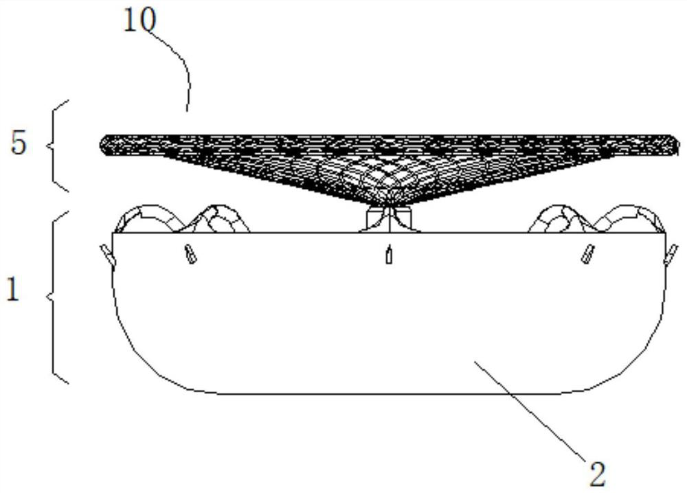
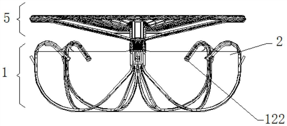
[0059] Embodiment 1 provides a left atrial appendage occluder 10 , including a fixed disk 1 and a sealing disk 5 . The distal end of the sealing disc 5 is connected with the fixed disc 1 . Wherein the sealing disk 5 can be made of at least one metal wire (such as nickel-titanium alloy wire) or biocompatible polymer wire with superelasticity and shape memory. Fix it, and then heat it into a flat shape or a disc shape. The shape is not limited, as long as it can block the opening of the tissue after being implanted in the body. The sleeve tube located at the proximal end of the sealing disc 5 can not only constrict the proximal end of the metal wire, but also be detachably connected to the distal end of the delivery device for delivering the occluder. The sleeve located at the distal end of the sealing disc 5 is not only used for converging the distal end of the wire, but also for connecting with the proximal end of the fixed disc 1 . In another embodiment, the sealing disc 5 ...

Embodiment 2

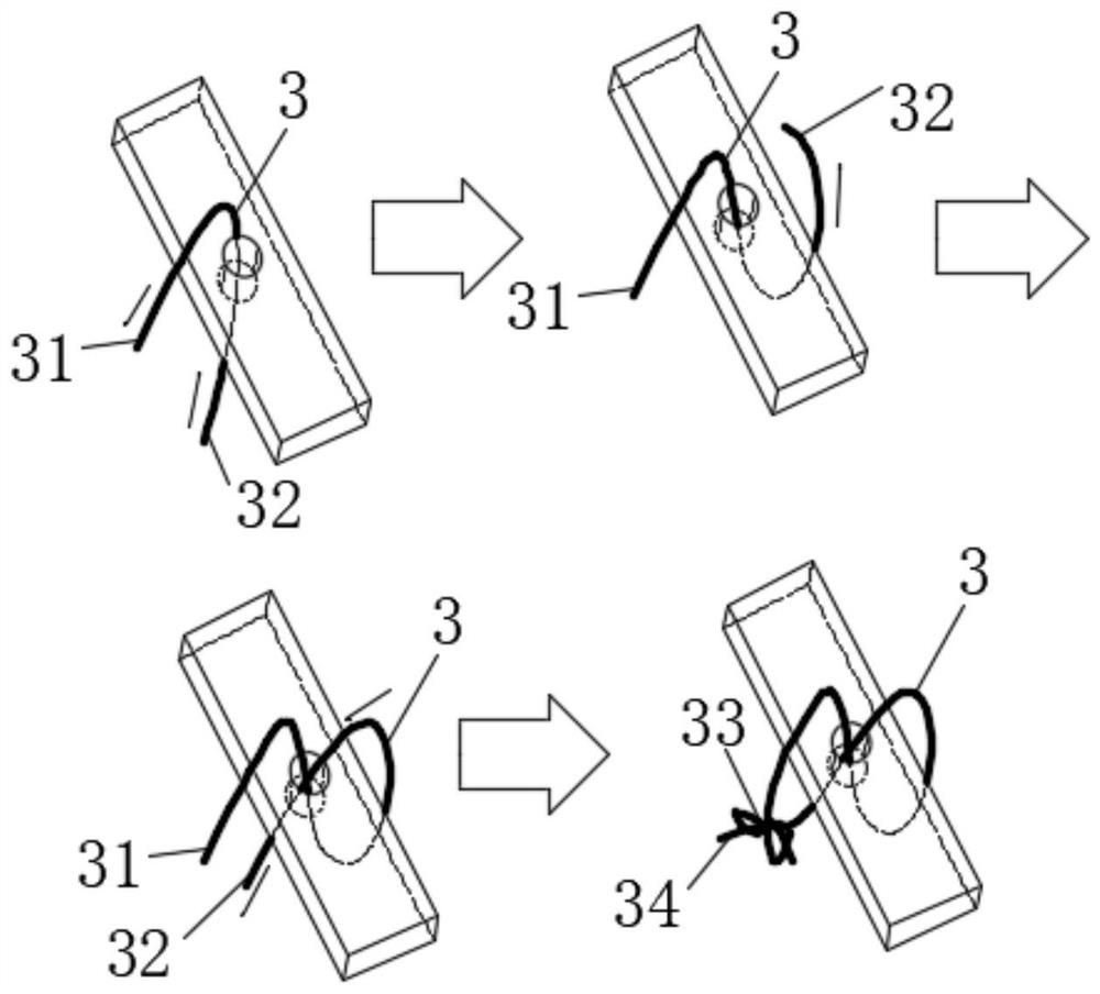
[0084] The parts of the fixed disk 1 in Embodiment 2 having the same structure as the fixed disk 1 in the above-mentioned embodiment will not be repeated here. The thread 4 runs continuously around the fixed disk 1 and the film body 2 , and the film body 2 and the fixed disk 1 are connected by the second sewing thread 4 . refer to Figure 18 with Figure 19As shown, the second suture 4 is continuously routed around the fixed disk 1 and the film body 2, and can form a continuous connection to the film body 2 around the periphery of the fixed disk 1, thereby increasing the number of rods or The binding force between the wires can avoid dislocation or twisting of some rods or wires inside the left atrial appendage, and ensure that the occluder can be smoothly deployed after being implanted inside the left atrial appendage, improving the success rate of the operation. The present invention defines "continuous routing" as sutures passing through at least three continuous suture p...


PUM

PropertyMeasurementUnit
Lengthaaaaaaaaaa
Diameteraaaaaaaaaa

Abstract

The invention discloses a left auricle occluder and a suturing method. The left atrial appendage occluder comprises a fixed disc, the fixed disc comprises a leading-out part and an anchoring part, the leading-out part extends towards the far end from a center of the fixed disc, the anchoring part is connected with the leading-out part and extends towards the near end through bending, the anchoring part comprises a plurality of suspended end parts with free ends, at least one layer of thin film body is arranged on the fixed disc, the thin film body comprises a main body part and a plurality of extension parts, the main body part at least covers part of the anchoring part, and the plurality of extension parts cover the plurality of suspended end parts. According to the technical scheme, after the at least one layer of thin film body covers the suspended end parts of the anchoring part, the thin film body can isolate the suspended end parts of the anchoring part, and therefore the phenomenon that the suspended end parts of the anchoring part is directly exposed after the occluder enters a left atrial appendage is avoided; and at the moment, when the fixed disc is fixed in the interior of left atrial appendage, the suspended end parts of the fixed disc cannot hook pectinate muscles of a heart, and when the occluder is not released ideally, effective adjustment can be carried out on the position of the occluder.

Description

technical field [0001] The invention relates to the technical field of interventional medical devices, in particular to a left atrial appendage and a suturing method. Background technique [0002] Atrial fibrillation (abbreviated as atrial fibrillation) is the most common sustained cardiac arrhythmia. The incidence of atrial fibrillation continues to increase with age, up to 10% of people over the age of 75. During atrial fibrillation, the frequency of atrial excitation reaches 300-600 beats per minute, and the heartbeat frequency is often fast and irregular. [0003] Non-valvular atrial fibrillation (Non-valvularAtrialFibrillation) refers to the rapid and disorderly beating of the atria, which has nothing to do with the ventricles. It is now thought to be produced by multiple interleaved wave-like reentrant electrical activity. This unstable electrical activity can cause atrial fibrillation of more than 350 beats / min. The heart rate of a normal person is 60-100 beats / mi...

Claims


Application Information

Patent Timeline
IPC IPC(8): A61B17/12
CPCA61B17/12122A61B17/12159A61B17/12031A61B17/12172A61B17/12177
Inventor 李安宁唐玉华刘建勇
Owner LIFETECH SCIENTIFIC (SHENZHEN) CO LTD
Why Eureka
Try Eureka