Disinfectant canning equipment

A disinfectant and canning technology, which is applied in the field of disinfectant canning equipment, can solve the problems of consuming physical strength of operators, reducing the canning efficiency of disinfectant canning equipment, and being unable to import disinfectant into the interior of the disinfectant tank, etc.

Pending Publication Date: 2021-06-15
甘肃润康药业有限公司
View PDF11 Cites 0 Cited by
  • Summary
  • Abstract
  • Description
  • Claims
  • Application Information

AI Technical Summary

Problems solved by technology

[0003] However, the existing disinfectant canning equipment has the following problems in application: when using solenoid valve equipment to control the export volume of disinfectant, it will be accompanied by power consumption and increase the use cost of disinfectant canning equipment, which is not environmentally friendly. concept, secondly, when the tank for storing disinfectant is large, the weight of the canned disinfectant tank will increase, and it will be difficult for the operator to move it laterally. The canning efficiency of the equipment. Finally, every time a new disinfectant tank is replaced, the operator needs to re-align the position manually. When the liquid outlet pipe and the opening end of the disinfectant tank are longitudinally misaligned, the disinfectant cannot be introduced into the disinfectant. inside of the tank

Method used


Image

  • Disinfectant canning equipment
  • Disinfectant canning equipment
  • Disinfectant canning equipment

Examples


Embodiment Construction

[0034] In order to further illustrate the various embodiments, the present invention provides accompanying drawings, which are part of the disclosure of the present invention, and are mainly used to illustrate the embodiments, and can be used to explain the operating principles of the embodiments in conjunction with the relevant descriptions in the specification, for reference Those of ordinary skill in the art should be able to understand other possible implementations and advantages of the present invention. The components in the figures are not drawn to scale, and similar component symbols are generally used to represent similar components.

[0035] According to an embodiment of the present invention, a disinfectant canning device is provided.

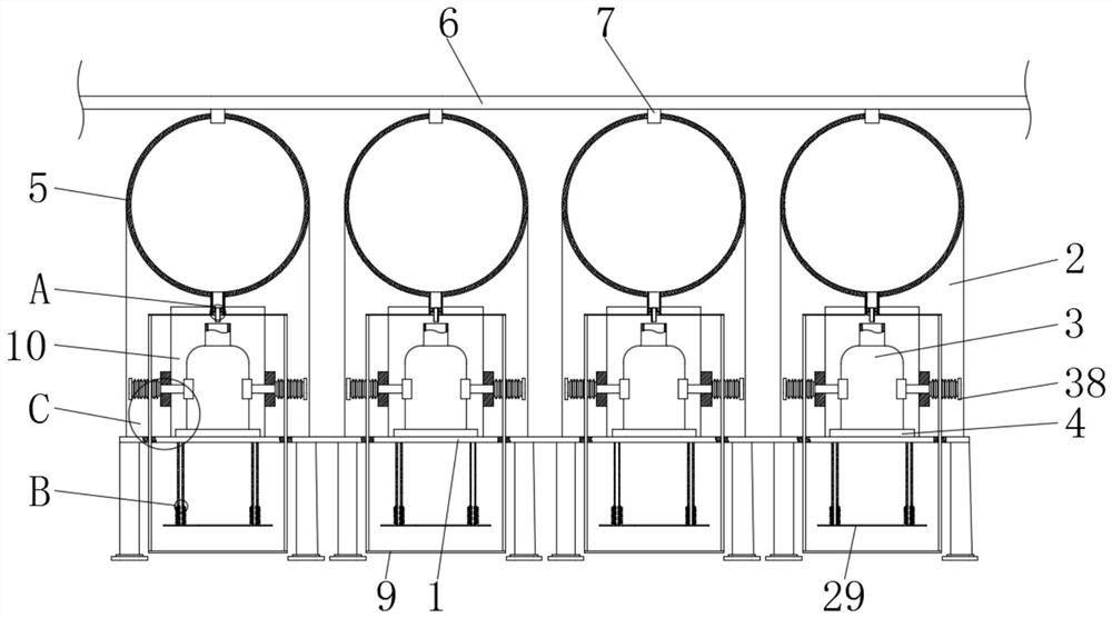
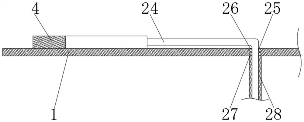
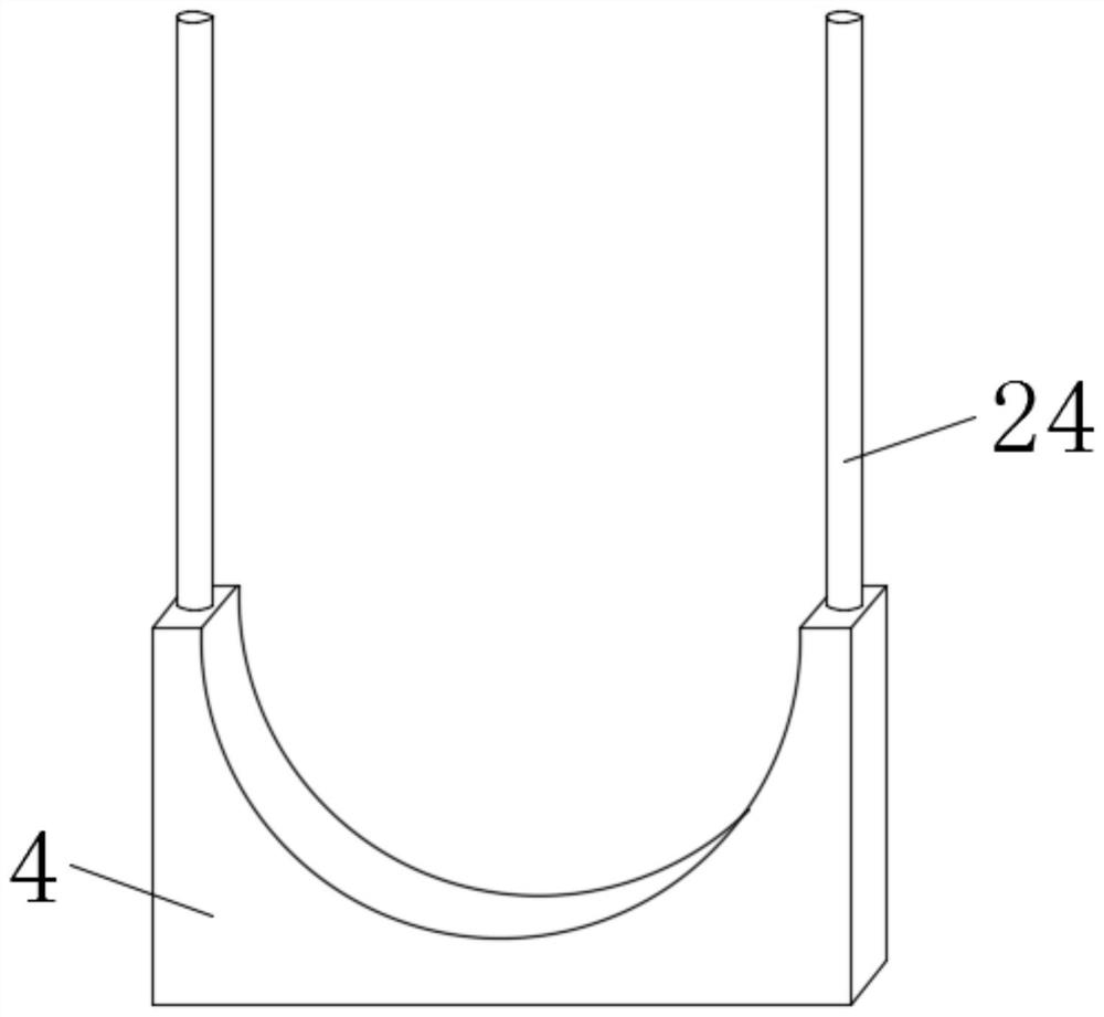
[0036] The present invention is further described in conjunction with accompanying drawing and specific embodiment now, as Figure 1-7 As shown, a disinfectant canning device according to an embodiment of the present invention inclu...


PUM


Abstract

The invention discloses disinfectant canning equipment which comprises a working plate and a liquid guide pipe, and four sets of supporting plates, four sets of can bodies and four sets of pushing arc-shaped plates are installed on the upper portion of the working plate. The disinfectant canning equipment has the beneficial effects that by treading liquid outlet plates, when disinfectant needs to be guided into one set of can bodies, an operator treads one set of treading liquid outlet plates with feet, and when one ends of one set of liquid discharging pipes are separated from one set of grooves, the disinfectant in one set of storage boxes is guided into one set of the can bodies via one group of the liquid outlet pipes and one set of the liquid discharging pipes. After the disinfectant is completely guided out, the feet of the operator are separated from one set of the treading liquid outlet plates, one set of telescopic springs abut against one set of the liquid discharging pipes, and when one ends of the set of the liquid discharging pipes are inserted into one set of the grooves, in the process, two sets of transverse plates drive two sets of guide rods and one set of the treading liquid outlet plates to be longitudinally reset to wait for the use next time. Other sets of treading liquid outlet plates can be operated in the same way, and by arranging the treading liquid outlet plates, the guide-out amount of the disinfectant does not need to be controlled by electrical equipment.

Description

technical field [0001] The invention relates to the field of disinfectant canning, in particular to a disinfectant canning equipment. Background technique [0002] Disinfectants are used to kill pathogenic microorganisms on the transmission medium to make them harmless, eliminate pathogenic microorganisms outside the human body, cut off the transmission of infectious diseases, and achieve the purpose of controlling infectious diseases. Disinfectants are based on their level of action It can be divided into sterilizers, high-efficiency disinfectants, medium-efficiency disinfectants, and low-efficiency disinfectants. Sterilizers can kill all microorganisms to meet the sterilization requirements, including formaldehyde, glutaraldehyde, ethylene oxide, peroxygen Acetic acid, hydrogen peroxide, chlorine dioxide, chlorine gas, copper sulfate, quicklime, ethanol, etc., when actually producing disinfectants, they need to be canned with disinfectant canning equipment, which has the a...

Claims


Application Information

Patent Timeline
IPC IPC(8): B65B3/06B65B43/54B65B39/00
CPCB65B3/06B65B43/54B65B39/00
Inventor 潘俊国潘江生
Owner 甘肃润康药业有限公司
Why Eureka
Try Eureka