Kitchen appliance glass high-temperature printing device and technology

A printing device and glass technology, applied in the direction of printing devices, printing, printing machines, etc., can solve the problems of no detection and reminder of electrical appliances, affecting the use of electrical appliances, unsatisfactory thermal conductivity and compressive strength of high borosilicate glass, etc.

Pending Publication Date: 2021-06-15
浙江银升新材料有限公司
View PDF10 Cites 0 Cited by
  • Summary
  • Abstract
  • Description
  • Claims
  • Application Information

AI Technical Summary

Problems solved by technology

[0003] Kitchen appliance glass is mostly glass installed on electrical appliances. Appliances will release a lot of heat when they are working. Traditional kitchen appliance glass is mostly high borosilicate glass. The thermal conductivity and compressive strength of high borosilicate glass are not ideal. It is heavy and easy to damage. The existing kitchen electric glass is connected to the electrical appliances by applying glass glue to connect the electrical appliances. When the electrical appliances fail, the direct contact between the glass panel and the coil will be uneven, easy to be damaged, and the safety factor is low.
The current kitchen appliances are often decorated with printed patterns on the glass, but the pattern printed on the glass is single, and it is a pattern when viewed from both sides. Various environmental factors in the kitchen will affect the use of appliances. Internal faults also occur, and the current electrical appliances do not have detection and reminder functions. When an electrical appliance fails, it is not easy to find the cause of the failure

Method used


Image

  • Kitchen appliance glass high-temperature printing device and technology
  • Kitchen appliance glass high-temperature printing device and technology
  • Kitchen appliance glass high-temperature printing device and technology

Examples


Embodiment 1

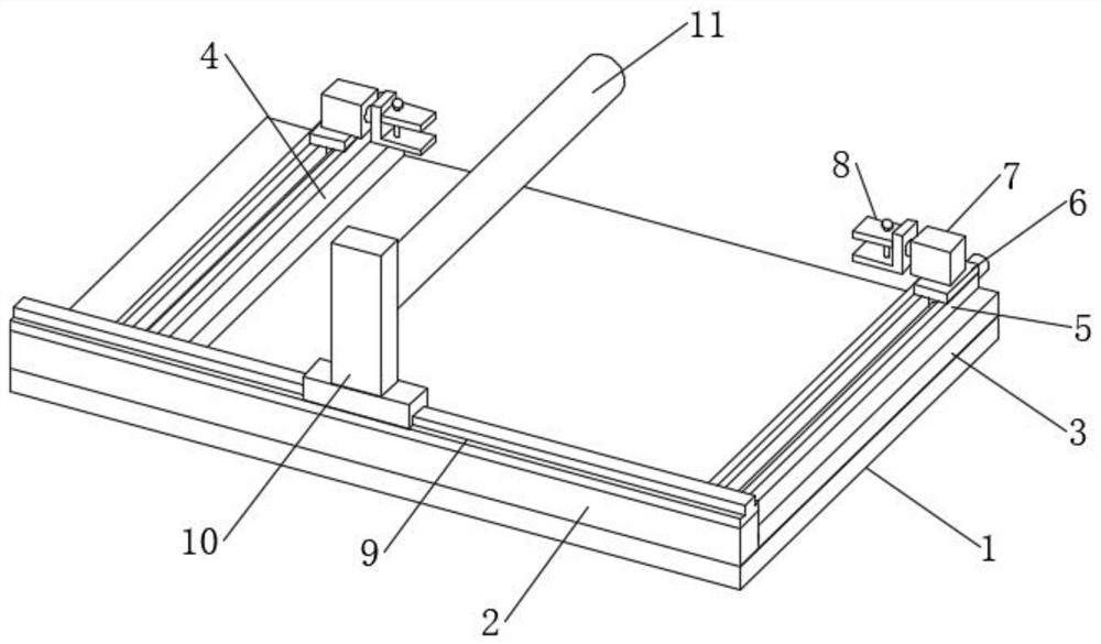
[0045] see Figure 1-3, a high-temperature printing device for kitchen electric glass and its technology, comprising a processing table 1, a longitudinal slide rail 2 is fixedly connected to the processing table 1, a fixed plate 3 is fixedly connected to one end of the longitudinal slide rail 2, and a sliding connection is made to the longitudinal slide rail 2 There is a movable plate 4, the fixed plate 3 and the movable plate 4 are fixedly connected with a transverse guide rail 5, the transverse guide rail 5 is slidably connected with a movable platform 6, and the movable platform 6 is fixedly connected with a stepping motor 7, and the power of the stepping motor 7 A mechanical clip 8 is fixedly connected to the output end, an electric slide rail 9 is laid on the top of the longitudinal slide rail 2, a slide table 10 is slidably connected to the electric slide rail 9, and a rolling cylinder 11 is connected to the slide table 10 in rotation, and the rolling cylinder 11 An elec...


PUM


Abstract

The invention discloses a kitchen appliance glass high-temperature printing device and technology, and belongs to the field of glass. According to the kitchen appliance glass high-temperature printing device and technology, a machining table is included, a longitudinal sliding rail is fixedly connected to the machining table, a fixed plate is fixedly connected to one end of the longitudinal sliding rail, and a movable plate is slidably connected to the longitudinal sliding rail. Transverse guide rails are fixedly connected to the fixed plate and the movable plate, a movable table is slidably connected to the transverse guide rails, a stepping motor is fixedly connected to the movable table, a mechanical clamp is fixedly connected to the power output end of the stepping motor, an electric sliding rail is laid at the top end of the longitudinal sliding rail, a sliding table is slidably connected to the electric sliding rail, and a rolling cylinder is rotationally connected to the sliding table. A deformable image can be printed between the two layers of glass, and a plurality of images printed by color-changing paint cover a basic graph so that a corresponding warning image can be generated on the glass when the surrounding environment of the glass is changed to a dangerous state, and convenience is brought to reminding and use.

Description

technical field [0001] The invention relates to the field of glass, and more specifically, to a high-temperature printing device for kitchen electric glass and its technology. Background technique [0002] Glass is an amorphous inorganic non-metallic material, generally made of various inorganic minerals (such as quartz sand, borax, boric acid, barite, barium carbonate, limestone, feldspar, soda ash, etc.) of. [0003] Kitchen appliance glass is mostly glass installed on electrical appliances. Appliances will release a lot of heat when they are working. Traditional kitchen appliance glass is mostly high borosilicate glass. The thermal conductivity and compressive strength of high borosilicate glass are not ideal. It is heavy and easy to be damaged. The existing kitchen appliance glass is connected to electrical appliances by coating glass glue to connect electrical appliances. When electrical appliances fail, the direct contact force between the glass panel and the coil is ...

Claims


Application Information

Patent Timeline
IPC IPC(8): B41F19/00B41M1/12B41M5/00B32B37/06B32B37/10
CPCB41F19/007B41M1/12B41M5/007B32B37/10B32B37/06
Inventor 舒佑炜
Owner 浙江银升新材料有限公司
Why Eureka
Try Eureka