Metal garbage recycling device based on extrusion principle
A technology of recycling and metal, which is applied in grain processing, presses, manufacturing tools, etc., can solve the problems of human injury, bacterial growth, splashing, etc., and achieve the effects of preventing bacterial growth, saving space, and simple structure
- Summary
- Abstract
- Description
- Claims
- Application Information
AI Technical Summary
Problems solved by technology
Method used
Image

Examples
Embodiment 1
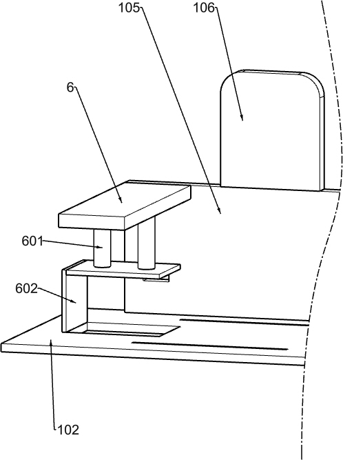
[0033] like Figure 1-8As shown, a metal waste recovery processing device based on the extrusion principle includes a first support plate 1, a first support rod 101, a second support plate 102, a third support plate 103, a fixed round block 104, a first fixed Plate 105, the second fixed plate 106, the pushing mechanism and the pressing mechanism, the first support plate 1 has two, and the two first support rods 101 are respectively fixedly installed on the right side of the two first support plates 1, and the second The support plate 102 is fixedly mounted on the upper ends of the two first support plates 1, the third support plate 103 is fixedly mounted on the upper right end of the two first support rods 101, the third support plate 103 is in contact with the second support plate 102, and the fixed circle The block 104 is fixedly mounted on the upper middle position of the third support plate 103, the two first fixed plates 105 are respectively fixedly mounted on the upper l...
Embodiment 2
[0036] like Figure 2-3 As shown, the pushing mechanism includes cylinder 2, fixed round bar 201, first fixed square bar 202, first slide bar 203, first spring 204, fixed block 205, second slide bar 206, second spring 207, slide Frame 208, the second fixed square rod 209 and push plate 210, cylinder 2 is fixedly installed on the fixed round block 104, and cylinder 2 runs through the left and right sides of fixed round block 104, and fixed round rod 201 is fixedly installed on the left end of the expansion rod of cylinder 2 , the first fixed square bar 202 is fixedly installed on the left end of the fixed round bar 201, the first sliding bar 203 is fixedly installed on the left end of the first fixed square bar 202, the first spring 204 is sleeved on the first sliding bar 203, and the fixed block 205 Fixedly installed on the lower side of the first fixed square bar 202, the second slide bar 206 is slidingly connected with the left and right sides of the fixed block 205, the sec...
Embodiment 3
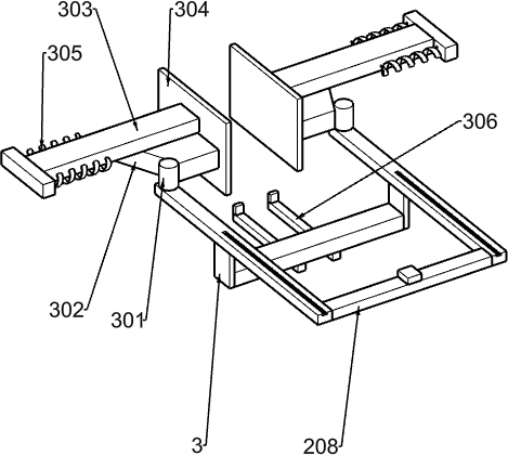
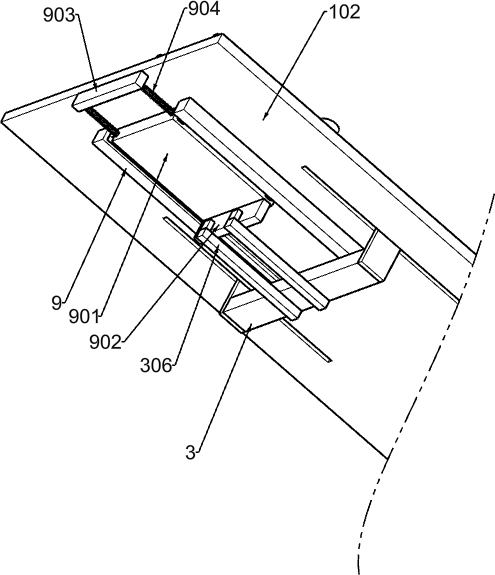
[0039] like Figure 4-5 As shown, the pressing mechanism includes a U-shaped frame 3, a first fixed column 301, a top plate 302, a push rod 303, a pressing plate 304, a third spring 305, a third slide bar 306, a fourth fixed plate 6, and a second fixed column. 601 and L-shaped plate 602, the U-shaped frame 3 is fixedly installed in the lower middle position of the slide frame 208, the U-shaped frame 3 is in sliding contact with the groove provided on the second support plate 102, and the two first fixed columns 301 are respectively fixedly installed on the On the front and rear sides of the upper part of the carriage 208, the two push rods 303 are respectively slidably mounted on the outer sides of the two first fixing plates 105, and the two pressure plates 304 are respectively fixedly mounted on the inner ends of the two push rods 303, and the two top plates 302 are respectively Fixedly installed on the outside of the two pressure plates 304, the two first fixed columns 301 ...
PUM
 Abstract
Description
Claims
Application Information
 - R&D
- Intellectual Property
- Life Sciences
- Materials
- Tech Scout
- Unparalleled Data Quality
- Higher Quality Content
- 60% Fewer Hallucinations
Browse by: Latest US Patents, China's latest patents, Technical Efficacy Thesaurus, Application Domain, Technology Topic, Popular Technical Reports.
© 2025 PatSnap. All rights reserved.Legal|Privacy policy|Modern Slavery Act Transparency Statement|Sitemap|About US| Contact US: help@patsnap.com