Railway tunnel limit detection method

A detection method and tunnel technology, which is applied in the direction of railway vehicle profile measuring devices, railway car body parts, railway auxiliary equipment, etc., and can solve problems such as difficult operations, bulky tunnel limit detection devices, and unsuitable field operations.

Active Publication Date: 2021-06-11
JILIN YINGCHONG TECH CO LTD
View PDF8 Cites 0 Cited by
  • Summary
  • Abstract
  • Description
  • Claims
  • Application Information

AI Technical Summary

Problems solved by technology

[0003] The existing tunnel limit detection device is relatively heavy and unsuitable for field work; due to the time limit of the skylight, it is difficult to complete the operation in a short time; the detection device is basically manually propelled, and the level of automation is low.

Method used


Image

  • Railway tunnel limit detection method
  • Railway tunnel limit detection method

Examples


Embodiment 1

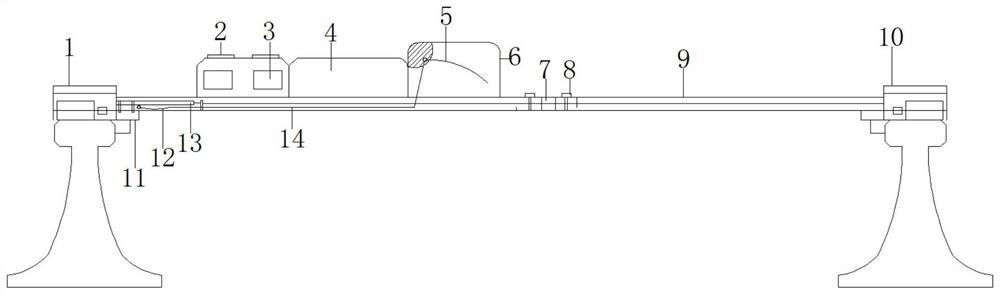
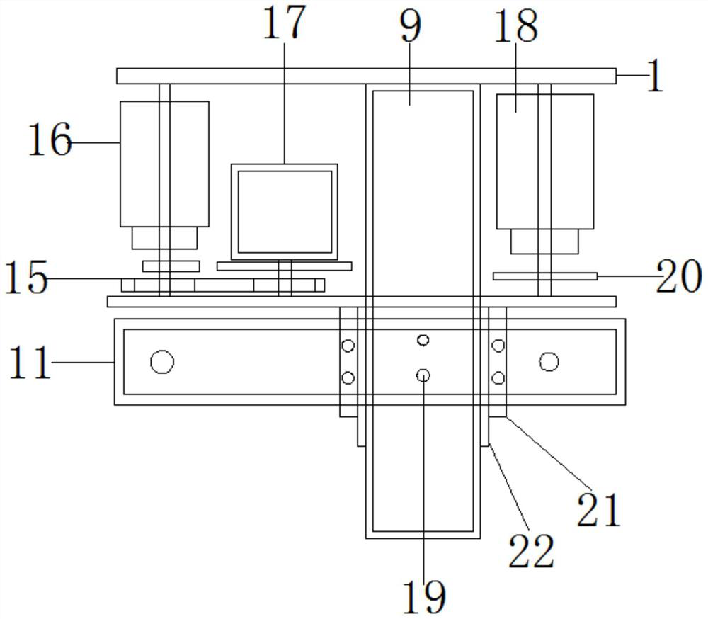
[0023] see figure 1 , 2 , a detection method for railway tunnel limits, comprising an integrated mobile mechanism 1 and an assembling movable mechanism 10, a detecting arm 9 is fixed between the integral moving mechanism 1 and the assembling movable mechanism 10 through a slot and a bolt, and the detecting arm 9 contacts Part of the folding shaft 7 is fixed by screws, and the folding shaft 7 is fixed by fixing bolts 8. There is a movable pulley frame 11 on the left side of the integrated moving mechanism 1, and the detection arm 9 is connected to the upper part of the movable pulley frame 11. The detection arm 9 and the movable pulley frame 11 Bolts a19 are fixed through threads, bolts b21 are provided on the front and rear sides of the detection arm 9, and guide rails 22 are provided between the bolts b21 and the detection arm 9, and the guide rails 22 are fixed on the movable pulley frame 11 by bolts b21, and the detection arm 9 Be provided with spring 12 between movable pu...

Embodiment 2

[0026] A method for detecting the boundary of a railway tunnel, comprising an integrated mobile mechanism 1, a management terminal 4, a boundary measuring instrument 2, and an assembleable mobile mechanism 10;

[0027] Methods as below:

[0028] S1: Install and fix the integrated mobile mechanism 1 and the assembled mobile mechanism 10 according to the tunnel data, fix the detection arm 9 through the folding shaft 7 and the fixing bolt 8, and perform the detection arm 9 and the integrated mobile mechanism through the movable pulley frame 11 and guide rail 22 1. After the connection with the movable mechanism 10 that can be assembled, after the fixing is completed, the above-mentioned device is installed. After the installation is completed, the initial work is completed;

[0029] S2: The gauge detection sensor detects the gauge according to the fixed position, the inclination sensor detects the inclination data, and transmits the data to the CPU and the control chip;

[0030]...


PUM


Abstract

The invention discloses a railway tunnel limit detection method, which comprises an integrated moving mechanism and an assembled moving mechanism, a detection arm is fixed between the integrated moving mechanism and the assembled moving mechanism through a clamping groove and a bolt, a folding shaft is fixed on the contact part of the detection arm through a screw, the folding shaft is fixed to the integrated moving mechanism through fixing bolts, stepping motors are arranged at the left side of the integrated moving mechanism, limit measuring instruments are arranged above the stepping motors, the range of charge of the limit measuring instruments is 90 degrees, two sets of stepping motors and two sets of limit measuring instruments are arranged, and the management end is arranged on the right sides of the stepping motors. The management end is composed of a CPU, a track gauge detection sensor, a tilt angle sensor, Bluetooth and a control chip, a handle is arranged in the right side of the management end and provided with a trigger, and the trigger is connected with one end of a connecting belt. The railway tunnel limit detection method has the advantages that the method is practical, portable and easy to carry, manual pushing is not needed, and rapid clearance detection operation of planing at any position of a tunnel is automatically achieved.

Description

technical field [0001] The invention relates to the technical field of railways, in particular to a detection method for railway tunnel boundaries. Background technique [0002] The railway tunnel gauge is one of the approaching gauges of railway buildings. In order to ensure that the train has enough driving space and driving safety when running in the tunnel, except for the rolling stock and the buildings and equipment that interact with the rolling stock, other buildings and equipment shall not be intruded within the limit. It can be seen that the tunnel is close to the limit detection It is of great significance to the safe operation of the railway. In recent years, along with the rapid development of electronic technology and computer technology, limit detection products based on new technologies have been introduced continuously, which can better meet the needs of limit detection operations. [0003] Existing tunnel limit detection devices are relatively heavy and un...

Claims


Application Information

Patent Timeline
Patent Type & Authority Applications(China)
IPC IPC(8): B61K9/08G01C9/00G01B21/16
CPCB61K9/08G01C9/00G01B21/16
Inventor 孙铁强李航周士超王磊孙伟
Owner JILIN YINGCHONG TECH CO LTD
Why Eureka
Try Eureka