Screen frame positioning system suitable for treadmill printing machine

A positioning system and printing machine technology, applied in printing machines, rotary printing machines, screen printing machines, etc., can solve the problems of increased production and processing costs, inconvenient adjustment, and the inconvenience of treadmill printing machines. The effect of improving stability

Pending Publication Date: 2021-06-11
浙江彩诺数码科技有限公司
View PDF1 Cites 2 Cited by
  • Summary
  • Abstract
  • Description
  • Claims
  • Application Information

AI Technical Summary

Problems solved by technology

However, the treadmill flat printing machine adopts rod-groove matching and hole-shaft matching for the positioning of the screen frame, which requires high matching precision between the guide rail and the positioning components, which will lead to an increase in production and processing costs, and It will make it very inconvenient to adjust the size specifications of different products; at the same time, when the treadmill printing machine with this structure shakes when the screen frame shakes during the printing process, the accumulation of position errors between multiple printing stations The effect will greatly affect the positioning of the screen frame during the continuous printing process, which will increase the probability of defective products and reduce printing efficiency, and even cause the treadmill printing machine to fail to work normally.

Method used


Image

  • Screen frame positioning system suitable for treadmill printing machine
  • Screen frame positioning system suitable for treadmill printing machine
  • Screen frame positioning system suitable for treadmill printing machine

Examples


Embodiment 1

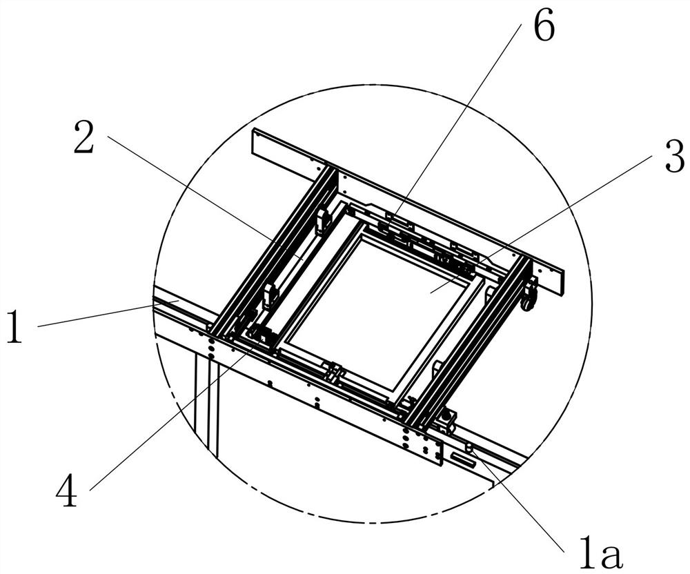
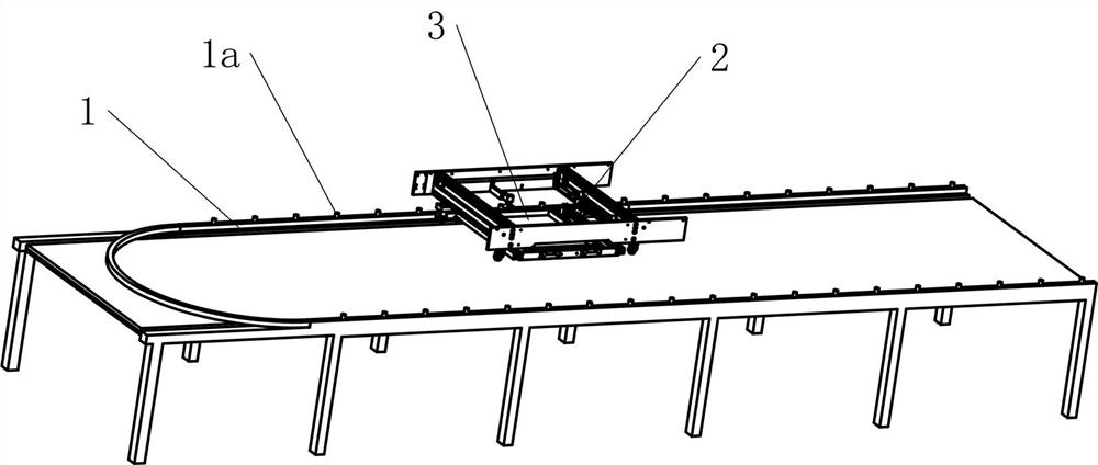
[0044] Embodiment 1: A screen frame guide rail positioning system suitable for a treadmill printing machine, including a guide rail 1 installed on the stand and extending along the X-axis direction for guiding the treadmill printing machine to walk. The upper surface of the guide rail 1 protrudes upwards to form several cylindrical positioning columns 1a, each positioning column 1a is arranged along the extending direction of the guide rail 1 and the adjacent two positioning columns 1a are spaced at the same distance, The positioning column 1a is installed and fixed in the X-axis direction and does not move any more. The walking system of the treadmill printing machine is fixedly installed with the guide rail 1 through the roller assembly clamped on both sides of the guide rail 1, and the driving wheel drives the printing machine to walk and move along the guide rail 1 on the platform surface. A net frame 2 for placing the screen frame 3 is movably installed on the treadmill p...

Embodiment 2

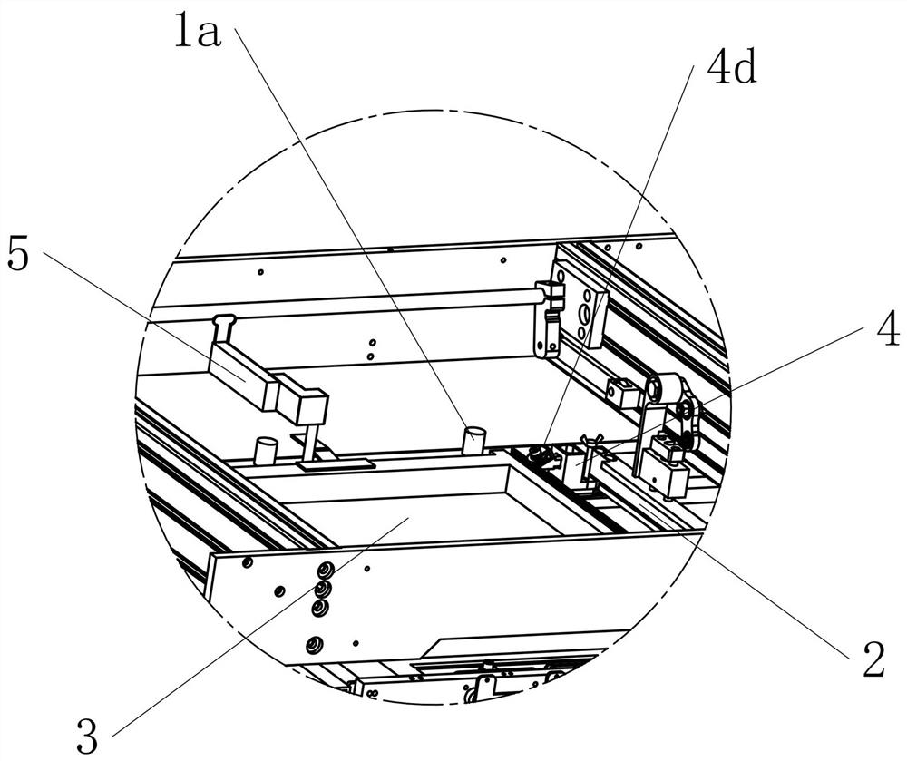
[0051] Embodiment 2: On the basis of Embodiment 1, the limit assembly 4d is integrated with the first positioning assembly 4, so that the first positioning assembly 4 includes a rotary roller whose rotation center axis is at a certain angle relative to the vertical direction 4e, the outer surface of the rotary roller 4e is a concave or convex arc-shaped curved surface, and the outer surface of the screen frame 3 used to abut against the outer surface of the rotary roller 4e is a corresponding convex or concave surface. Arc-shaped surface. At this time, the rotating roller 4e can provide the screen frame 3 with an abutting force horizontally along the X-axis direction and vertically along the Z-axis direction. At the same time, when the screen frame 3 moves along the Y-axis direction, the structure of the rotary roller 4e can effectively reduce the frictional resistance when the screen frame 3 moves through its own rotation, making the positioning process more efficient, and th...


PUM


Abstract

The invention aims to provide a screen frame positioning system suitable for a treadmill printing machine, on the basis that an internal program controls the main walking process of the printing machine, a positioning structure enabling a printing screen frame to abut against and be attached to a positioning column located on a guide rail is arranged, and accurate positioning of the printing screen frame is achieved; an identification or induction detection device does not need to be added, so that the manufacturing cost is lowered; according to the positioning system, positioning of the printing screen frame is more stable and reliable, and the situation that when the position of the screen frame is controlled only through an internal program, the printing quality of a product is reduced due to introduction of external interference factors or continuously accumulated errors is effectively avoided; and meanwhile, collision impact generated by the positioning mode can be effectively relieved through a vibration reduction reset spring arranged in the system, and the working stability and durability of equipment are improved.

Description

technical field [0001] The invention relates to the field of treadmill printing machine equipment, in particular to a screen frame positioning system suitable for treadmill printing machines. Background technique [0002] Screen printing is beautiful in color and bright in color, and can also produce different three-dimensional effects. It is also suitable for flat printing of various materials and has a wide range of applications. Because of its uniqueness, it is unmatched by other flat printing methods. Therefore, the screen printing method has continued to develop until now. Screen printing uses the screen set on the printing machine as the plate base, and uses the basic principle that the graphic part of the screen printing plate can pass through the dye, and the non-graphic part of the mesh cannot pass through the dye. Pour the dye into one end of the screen printing plate, apply a certain pressure on the dye part on the screen printing plate with a scraper, and move t...

Claims


Application Information

Patent Timeline
IPC IPC(8): B41F15/14B41F15/36
CPCB41F15/14B41F15/36
Inventor 周士勇朱海龙
Owner 浙江彩诺数码科技有限公司
Why Eureka
Try Eureka