
Magnetic suction type plate dust-free drilling equipment

A kind of drilling equipment, magnetic suction technology, applied in the direction of drilling/drilling equipment, boring/drilling, metal processing equipment, etc., can solve the problems of difficult cleaning, affecting the workshop environment, difficult cleaning, etc., to achieve easy cleaning , avoid waste leakage, increase the effect of drilling accuracy

Inactive Publication Date: 2021-06-11
李红
View PDF0 Cites 1 Cited by
  • Summary
  • Abstract
  • Description
  • Claims
  • Application Information

AI Technical Summary

Problems solved by technology

[0002] In the process of plate processing, some plates need to be drilled. Drilling equipment is required for drilling. Factory processing usually uses automatic drilling machines as the main drilling equipment. During the drilling process, a large amount of waste will be generated, which is not easy to clean up. And affect the environment of the workshop, more serious will lead to equipment failure
[0003] Existing drilling equipment usually adopts the integrated method of drilling and suction for dust removal, that is, a dust suction pipe wrapping the drill bit is provided on the side of the drilling mechanism, and the waste chips turned out by the drill bit on the surface of the plate will be sucked during the drilling process. In addition, when the waste at the bottom of the plate cannot be removed after perforation, a large amount of waste at the bottom of the plate falls into the gaps on the drilling equipment, and it is still difficult to clean, that is, it cannot effectively remove dust.

Method used


Image

  • Magnetic suction type plate dust-free drilling equipment
  • Magnetic suction type plate dust-free drilling equipment
  • Magnetic suction type plate dust-free drilling equipment

Examples


Embodiment Construction

[0021] The following will clearly and completely describe the technical solutions in the embodiments of the present invention with reference to the accompanying drawings in the embodiments of the present invention. Obviously, the described embodiments are only some, not all, embodiments of the present invention.

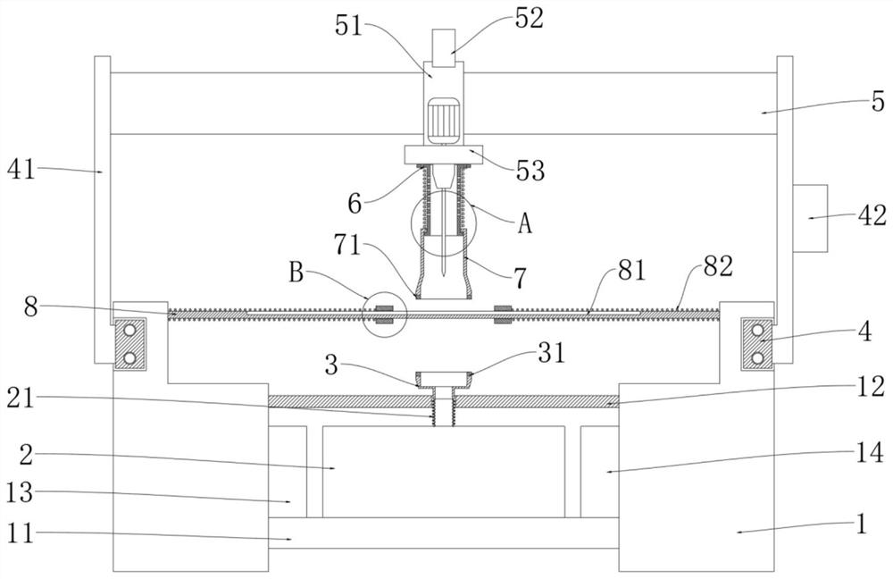
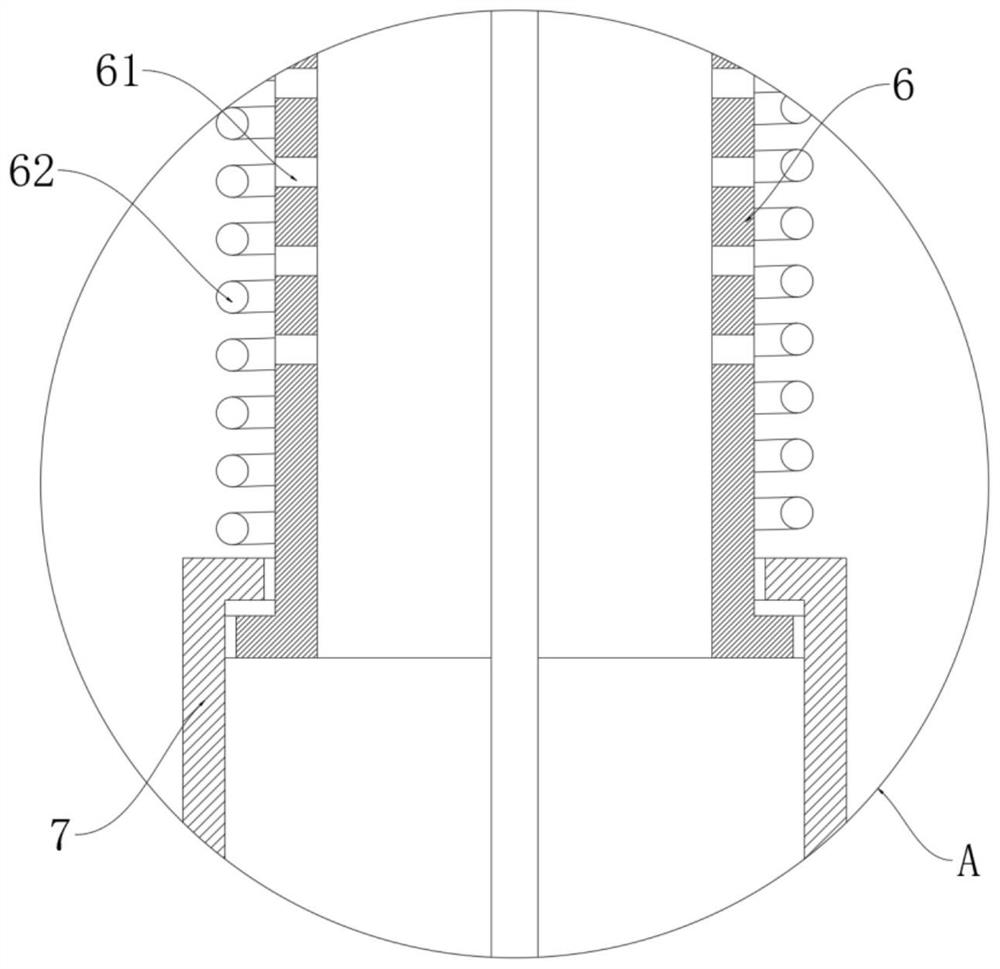
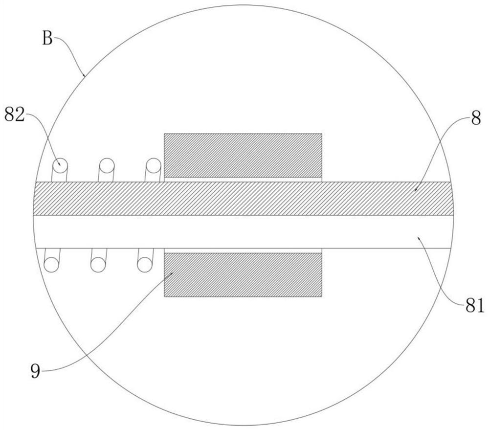
[0022] refer to Figure 1-4 , a magnetic dust-free plate drilling equipment, including two symmetrically arranged pedestals 1, each pedestal 1 is slidingly installed on the outside of the cylinder 4, each cylinder 4 is equipped with a movable plate 41, two movable The upper end of the plate 41 is jointly slidably equipped with a magnetic slide plate 5, the sliding sleeve on the magnetic slide plate 5 is provided with a sliding sleeve 51, the lower end of the sliding sleeve 51 is equipped with a support plate 53, and the bottom surface of the support plate 53 is equipped with a first-level sealing tube 6, the first-level sealing The lower end of the tube 6 is slidingl...


PUM


Abstract

The invention discloses magnetic suction type plate dust-free drilling equipment which comprises two symmetrically-arranged pedestals, an air cylinder is slidably installed on the outer side of each pedestal, a movable plate is installed on each air cylinder, a magnetic sliding plate is jointly slidably installed at the upper ends of the two movable plates, and a sliding sleeve is slidably arranged on the magnetic sliding plate in a sleeving mode. A supporting plate is installed at the lower end of the sliding sleeve, a first-stage sealing pipe is installed on the bottom face of the supporting plate, and the lower end of the first-stage sealing pipe is slidably sleeved with a second-stage sealing pipe. The upper surface and the lower surface of a drilling area of the plate are always kept to be sealed through the strong magnetic adsorption effect between an upper magnetic rubber ring and a lower magnetic rubber ring, dust-free drilling is achieved, the magnetic suction type plate dust-free drilling equipment is more environmentally friendly, automatic centering fixing is achieved through cooperation of an adjusting rod and a clamping plate, the drilling precision is improved, and the surface of the plate is convenient to clean; and a plurality of air inlet holes are formed in the pipe wall of the first-stage sealing pipe, so that the drill bit can be flushed by airflow during negative-pressure dust removal, and the dust removal and scrap removal capacity is further improved.

Description

technical field [0001] The invention relates to the field of drilling equipment, in particular to a magnetic suction type dust-free drilling equipment for plates. Background technique [0002] In the process of plate processing, some plates need to be drilled. Drilling equipment is required for drilling. Factory processing usually uses automatic drilling machines as the main drilling equipment. During the drilling process, a large amount of waste will be generated, which is not easy to clean up. And affect the environment of the workshop, more serious will lead to equipment failure. [0003] Existing drilling equipment usually adopts the integrated method of drilling and suction for dust removal, that is, a dust suction pipe wrapped around the drill bit is provided on the side of the drilling mechanism, and the waste chips turned out by the drill bit on the surface of the plate will be sucked during the drilling process. In addition, after the perforation, the waste chips a...

Claims


Application Information

Patent Timeline
Patent Type & Authority Applications(China)
IPC IPC(8): B23B41/00B23B47/00B23Q3/06B23Q11/00B23Q11/08
CPCB23B41/00B23B47/00B23Q3/06B23Q11/0046B23Q11/08
Inventor 李红霍彦华
Owner 李红
Learn More