
Reaming device with synchronous adjusting function and for flange structure machining

A technology of synchronous adjustment and function, applied in the direction of manufacturing tools, metal processing equipment, safety equipment, etc., can solve the problems of inconvenience, inability to quickly adjust the reaming position, inconvenient fast centering of flanges, etc., and achieve high applicability.

Inactive Publication Date: 2021-06-11
訾坤
View PDF2 Cites 0 Cited by
  • Summary
  • Abstract
  • Description
  • Claims
  • Application Information

AI Technical Summary

Problems solved by technology

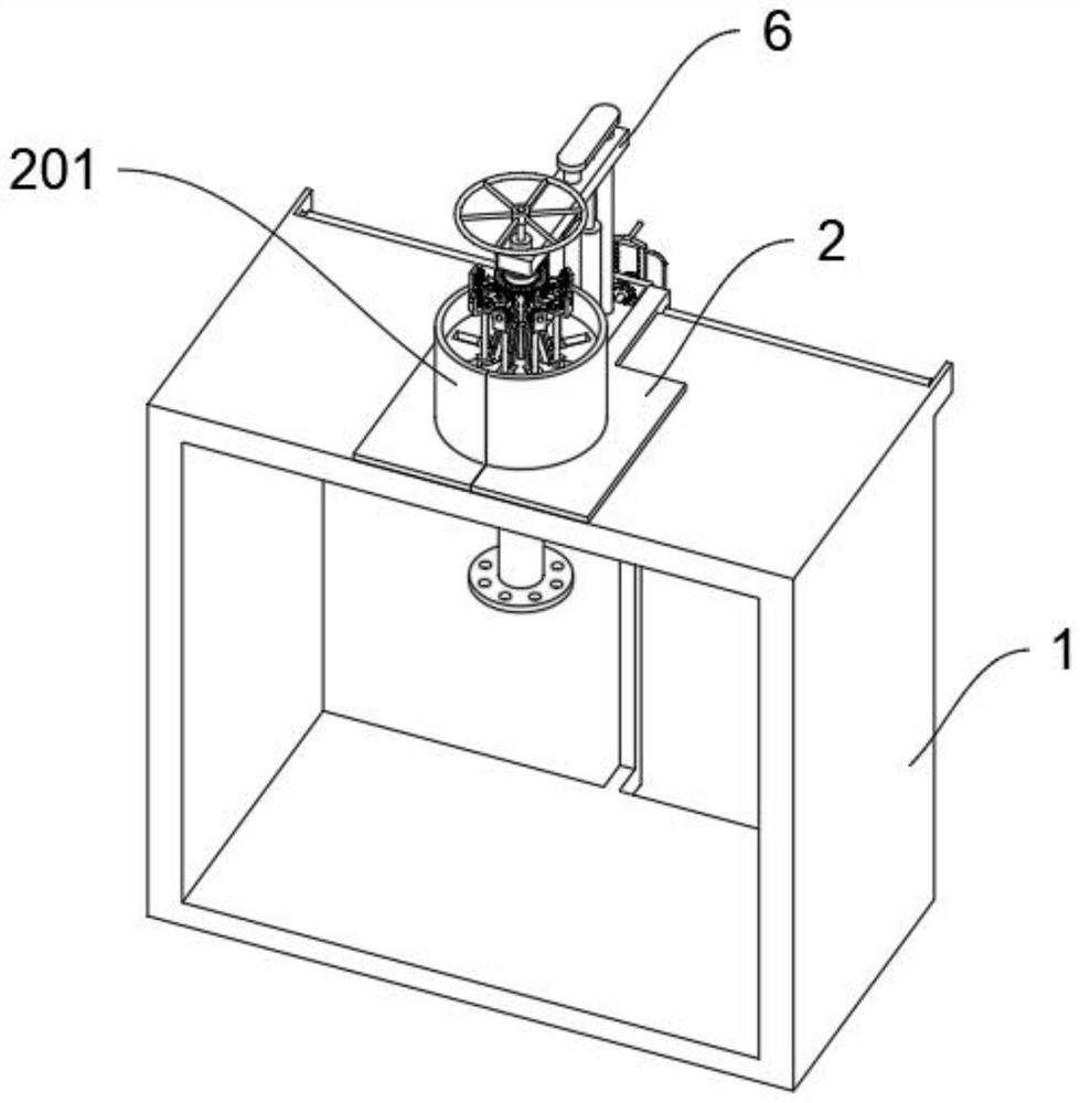
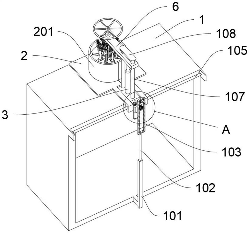
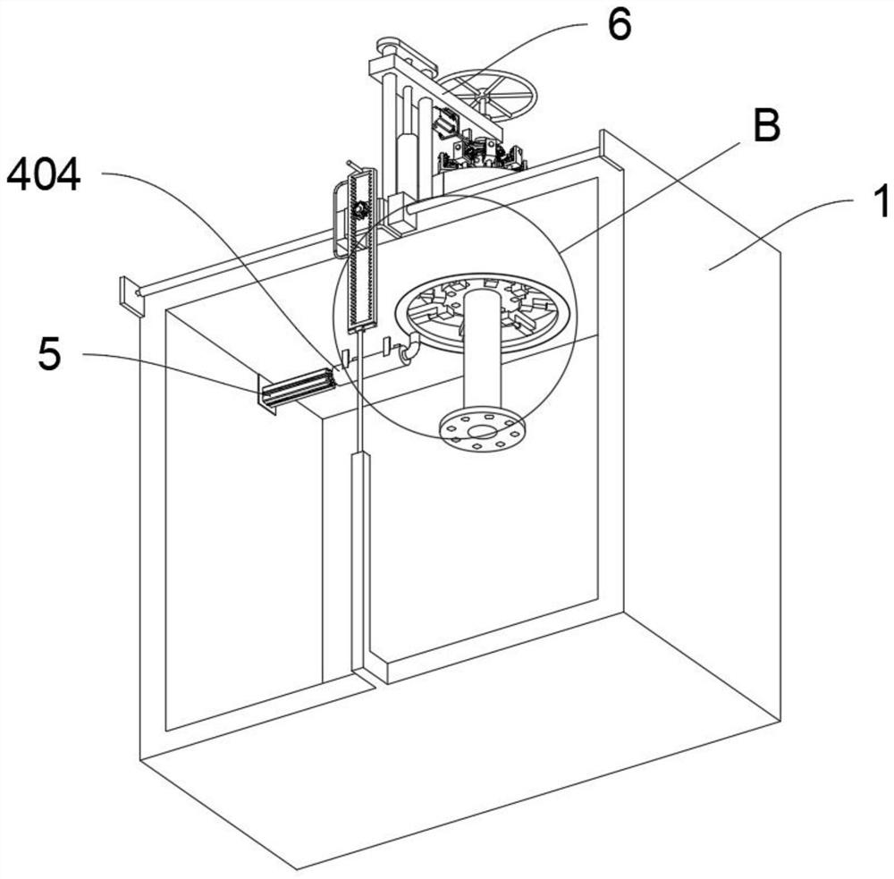
[0007] The object of the present invention is to provide a hole reaming device with synchronous adjustment function for flange structure processing, to solve the problem that the currently used hole reaming device proposed in the above background technology mainly reams a single hole after the flange is positioned , does not have the function of quickly adjusting the reaming position according to the diameter of the pipe, and it is inconvenient to quickly adjust the drilling action according to the different hole positions of the flange structure. It is inconvenient to quickly center and fix the problem according to different types of flanges.

Method used


Image

  • Reaming device with synchronous adjusting function and for flange structure machining
  • Reaming device with synchronous adjusting function and for flange structure machining
  • Reaming device with synchronous adjusting function and for flange structure machining

Examples


Embodiment Construction

[0031] The following will clearly and completely describe the technical solutions in the embodiments of the present invention with reference to the accompanying drawings in the embodiments of the present invention. Obviously, the described embodiments are only some, not all, embodiments of the present invention.

[0032]In the description of the present invention, unless otherwise stated, the meaning of "plurality" is two or more; the terms "upper", "lower", "left", "right", "inner", "outer" , "front end", "rear end", "head", "tail", etc. indicate the orientation or positional relationship based on the orientation or positional relationship shown in the drawings, and are only for the convenience of describing the present invention and simplifying the description, rather than Nothing indicating or implying that a referenced device or element must have a particular orientation, be constructed, and operate in a particular orientation should therefore not be construed as limiting t...


PUM


Abstract

The invention discloses a reaming device with a synchronous adjusting function and for flange structure machining, and relates to the technical field of flange machining. The problem that a currently-used reaming device is mainly used for reaming a single hole after a flange is positioned and does not have the function of quickly adjusting the reaming position according to different pipeline diameters are solved. The reaming device with the synchronous adjusting function and for flange structure machining comprises a frame seat. Two sets of buckle seats are arranged on the rear side of the top of the frame seat in a sliding manner. A mounting hole is formed in the front side of the top of the frame seat. A U-shaped frame is fixedly arranged in the middle of the rear side of the frame seat, and two sets of side lead screws are rotationally arranged on the two sides of the U-shaped frame. An octagonal nut, a connecting rod and a drill rod sliding seat are arranged, the function of quickly adjusting the reaming position is provided for the reaming device, a drill rod, an L-shaped frame and a hexagonal telescopic shaft synchronously stretch out and draw back to move while the drill rod sliding seat moves, and the drilling position of the reaming device is adjusted, so that quick adjustment can be carried out according to different types of flanges.

Description

technical field [0001] The invention relates to the technical field of flange processing, in particular to a hole reaming device with synchronous adjustment function for flange structure processing. Background technique [0002] Flanges, also known as flange flanges or flanges, are parts that are connected to each other between pipes. They are used for connection between pipe ends, and are also useful for flanges on the inlet and outlet of equipment. The connection between two devices, such as reducer flange, etc. [0003] After searching, for example, the patent No. CN109382474A discloses a flange reaming device that can detect the aperture of the flange, including a body. The front of the body is provided with an inner port, and a vertical rod is fixedly installed inside the inner port. The number of the vertical rods is two, and the two vertical rods are symmetrical about the center of the body, and a pneumatic cylinder is fixedly installed on the top of the body. The f...

Claims


Application Information

Patent Timeline
IPC IPC(8): B21D31/04B21D55/00
CPCB21D31/046B21D55/00
Inventor 訾坤
Owner 訾坤
Learn More