
Coal gangue screening equipment

A screening equipment and technology for coal gangue, which are applied in solid separation, separation of solids from solids by air flow, chemical instruments and methods, etc., can solve the problems of containing and affecting the quality of gangue particles, and achieve the effect of improving quality

Active Publication Date: 2021-06-11
青岛矿冶能源科技有限公司
View PDF14 Cites 0 Cited by
  • Summary
  • Abstract
  • Description
  • Claims
  • Application Information

AI Technical Summary

Problems solved by technology

[0003] Gangue can be used as building materials or for backfilling mine pits. The gangue used as building materials or for backfilling pits needs to be crushed to a certain particle size, and gangue particles need to be crushed Screening, the current screening method generally uses a filter screen for screening, but it is difficult to remove the powder in the gangue particles by using a filter screen for screening, resulting in part of the powder in the gangue particles, so that the quality of the gangue particles is affected

Method used

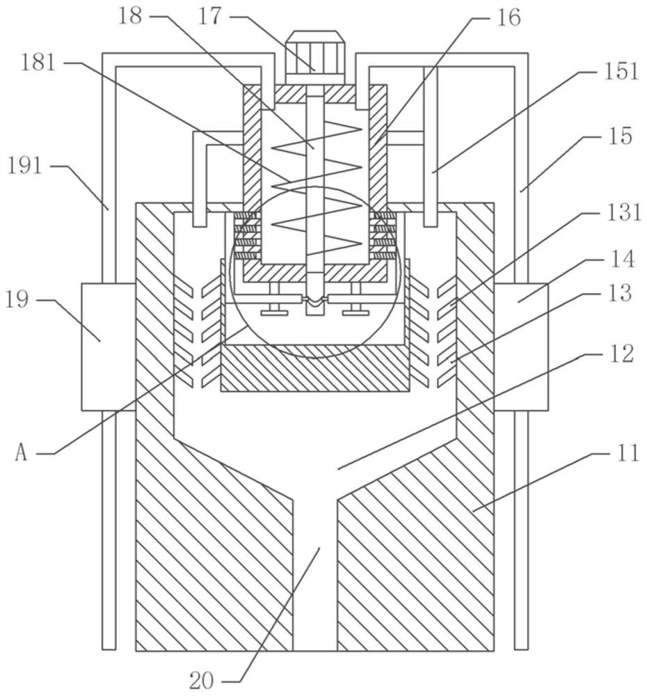
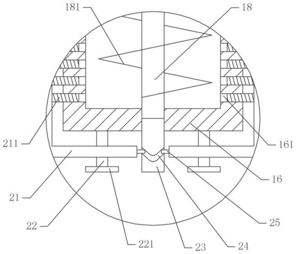
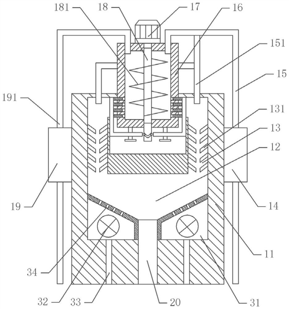

Image

  • Coal gangue screening equipment
  • Coal gangue screening equipment
  • Coal gangue screening equipment

Examples


Embodiment 1

[0031] Basic as attached figure 1 And attached figure 2 Shown: a coal gangue screening equipment, including a frame, a body 11 is fixed by bolts on the frame, a screening barrel 16 is fixed by bolts on the upper part of the body 11, a first negative pressure machine 19 is fixed by bolts on the body 11, the first The inlet of the negative pressure fan 32 is connected with the material box, and the outlet of the first negative pressure fan 32 is connected with the feeding pipe 191 , and the feeding pipe 191 is connected with the screening barrel 16 . The sieving barrel 16 is provided with a stirring mechanism, the stirring mechanism includes a motor 17, the output shaft of the motor 17 is fixed with a stirring shaft 18 by coaxial bolts, the stirring shaft 18 is welded and fixed with stirring blades 181, the two sides of the sieving barrel 16 bottom There are several screening holes 161 on the wall, and the lower end of the stirring shaft 18 is fixed with a rotating shaft 23 by...

Embodiment 2

[0038] The difference between embodiment two and embodiment one is that, as attached image 3As shown, there are several dust removal chambers 31 on the body 11. Fans 32 bolted on the body 11 are arranged in the dust removal chambers 31. The fan 32 is an exhaust fan 32. There is an air hole 34 communicating with the collection chamber 12 , the air inlet of the fan 32 is in communication with the air passage 33 , and the air outlet of the fan 32 faces the air hole 34 .

[0039] When the fan 32 works, the fan 32 inhales the outside air through the air channel 33, and the fan 32 blows the gas into the collection chamber 12 through the air hole 34, and the gas flows to blow off the dust on the gangue particles, so that the dust on the gangue particles is reduced. , to further improve the quality of gangue particles. Under the effect of the dedusting mechanism, the gas flows upwards and blows off the dust on the gangue particles when passing through the discharge channel 13. At th...


PUM


Abstract

The invention relates to the technical field of stone crushing, and discloses coal gangue screening equipment. The equipment comprises a rack, wherein a body is fixedly arranged on the rack, a screening barrel is fixed to the body, the screening barrel is communicated with a feeding mechanism, and the screening barrel is communicated with a dust removal mechanism; a stirring mechanism driven by a power part is arranged in the screening barrel, a plurality of screening holes are arranged in the side wall of the screening barrel, a discharging channel communicated with the screening holes is arranged in the body, and the discharging channel is communicated with the dust removal mechanism; and a plurality of vibrating pieces are arranged on the side wall of the discharging channel, the discharging channel is communicated with a collecting cavity, and the collecting cavity is communicated with a discharging opening of the outside. The equipment is simple in structure, dust in gangue particles is screened out, and the quality of the gangue particles is improved.

Description

technical field [0001] The invention relates to the technical field of stone crushing, and specifically discloses coal gangue screening equipment. Background technique [0002] Gangue, stones mixed in the coal seam, containing a small amount of combustibles, not easy to burn, commonly known as "gangue". During the mining process, the crushed stones extracted from the underground or mixed into the ore, and the thin rock layer in the middle of the coal seam are called "interbed stones". The gangue pile on the ground of the mine is called "the gangue hill", and the gangue can be used as a raw material for building materials. [0003] Gangue can be used as building materials or for pit backfilling. The gangue used as building materials or for backfilling pits needs to be crushed to a certain particle size, and the gangue particles need to be screened. Currently, the screening method generally uses a filter sieve for screening. However, using It is difficult to sieve the powder...

Claims


Application Information

Patent Timeline
Patent Type & Authority Applications(China)
IPC IPC(8): B07B4/00B07B11/00B08B1/04B08B7/02
CPCB07B4/00B07B11/00B08B7/02B08B1/32
Inventor 武晓敏贾丽雷隽娴屈昌辉
Owner 青岛矿冶能源科技有限公司
Learn More