
Electro precipitator utilizing ionic wind to assist in dust collection and polar plate

A technology of electrostatic precipitator and dust collecting plate, which is applied in electrode structure, electrode cleaning, electrostatic separation, etc., can solve the problems of large impact of water spray, unfavorable emission diffusion, and large temperature drop of flue gas, etc., to improve dust removal efficiency, The effect of expanding the scope of application and reducing the negative impact

Pending Publication Date: 2021-06-11
XI'AN UNIVERSITY OF ARCHITECTURE AND TECHNOLOGY
View PDF0 Cites 2 Cited by
  • Summary
  • Abstract
  • Description
  • Claims
  • Application Information

AI Technical Summary

Problems solved by technology

Although good tempering effect can be obtained, secondary pollution caused by sulfuric acid and ammonia, and the toxicity of diethylamine and sodium chloride are relatively high, which can easily lead to equipment blockage
Domestic research is mainly on water-based conditioning agents. Although the problems caused by the above-mentioned schemes will not occur, there are new problems that the large amount of water sprayed affects the dust removal effect, and the large temperature drop of the flue gas is not conducive to the diffusion of emissions.

Method used


Image

  • Electro precipitator utilizing ionic wind to assist in dust collection and polar plate
  • Electro precipitator utilizing ionic wind to assist in dust collection and polar plate
  • Electro precipitator utilizing ionic wind to assist in dust collection and polar plate

Examples


Embodiment Construction

[0043] The present invention will be described in detail below in conjunction with the accompanying drawings and specific embodiments, where the schematic embodiments and descriptions of the present invention are used to explain the present invention, but not to limit the present invention.

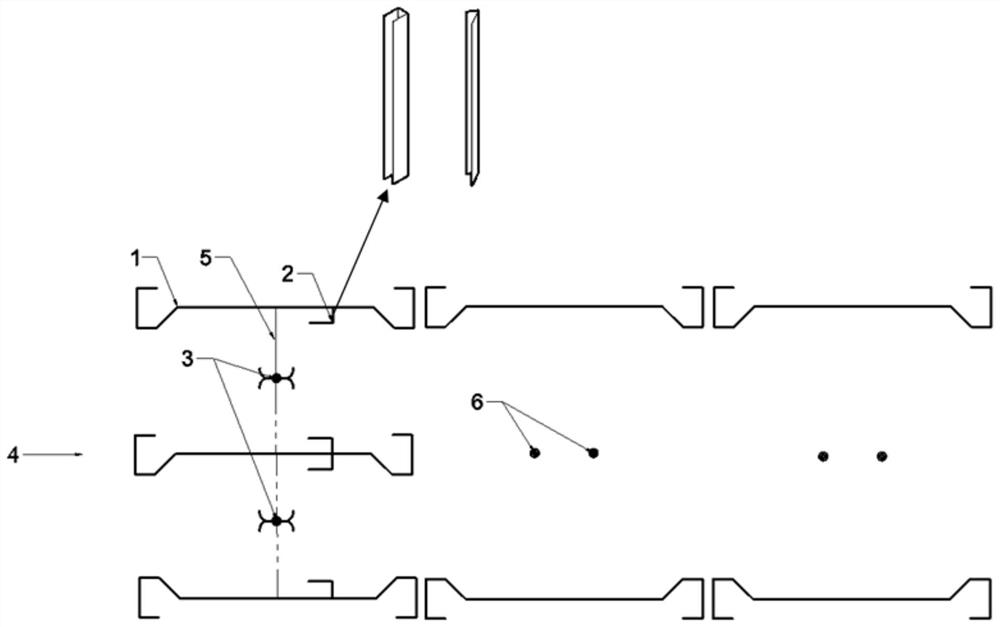
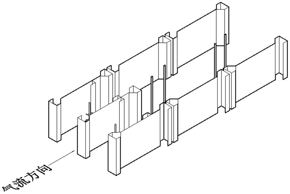
[0044] like figure 1 , figure 2 As shown, the embodiment of the present invention provides an electric precipitator that uses ion wind to assist dust collection, including a front electric field and a rear electric field formed by a symmetrical arrangement of several pairs of electric dust collector dust collection plates 1 with the same structure, and the electric precipitator collects dust The pole plate 1 is a panel and an end plate, the end plate is connected to both ends of the panel, the end plate is a bow-shaped plate, one end of the bow-shaped plate is a trapezoidal arch, and one end is bent to open, the opening faces the airflow to the back side, and the opening of the bow-shape...


PUM


Abstract

The invention discloses an electro precipitator utilizing ionic wind to assist in dust collection and a polar plate. Theelectro precipitator comprises a front electric field and a rear electric field which are formed by symmetrically arranging a plurality of pairs of electro precipitator dust collection polar plates of the same structure, wherein barbed wire discharge electrodes are arranged between the electro precipitator dust collection polar plates of the front electric field, long-groove-shaped frame-shaped plates of symmetrical structures are arranged on the inner sides of the electro precipitator dust collection polar plates at the rear parts of the barbed wire discharge electrodes to form a cavity, and the opening direction of the cavity faces an airflow inlet; round wire discharge electrodes are arranged between the electro precipitator dust collection polar plates of the rear electric field; and the distance between the electro precipitator dust collection polar plates of the front electric field is smaller than that between the electro precipitator dust collection polar plates of the rear electric field. According to the novel polar plates with the cavity, fine particles can be effectively captured by utilizing ionic wind generated by discharging, the dust removal efficiency of the electric dust remover on dust with high and low specific resistances can be improved by utilizing the electrostatic shielding effect of the cavity, the application range of the electro precipitator on dust with different specific resistances is expanded, and therefore, the overall dust collection efficiency is improved.

Description

technical field [0001] The invention relates to an electric precipitator, specifically an electric precipitator and an anode plate which use ion wind to assist dust collection. Background technique [0002] Fine solid particle pollutants in air pollutants are an important factor affecting environmental quality and human health. The equipment for controlling particle pollutants is a dust collector designed based on different principles. Bag type dust collector, cyclone dust collector, electrostatic precipitator, wet dust collector and composite dust collector are the main dust removal equipment on the market at present. With the increasingly stringent pollutant discharge standards, all kinds of dust collectors need to be continuously improved and perfected to meet the requirements of pollutant discharge standards. [0003] The electrostatic precipitator ionizes the gas through the discharge of the discharge electrode, and the particle pollutants obtain electrons to be charge...

Claims


Application Information

Patent Timeline
Patent Type & Authority Applications(China)
IPC IPC(8): B03C3/40B03C3/78
CPCB03C3/40B03C3/78
Inventor 闫东杰张子昂李振强玉亚
Owner XI'AN UNIVERSITY OF ARCHITECTURE AND TECHNOLOGY
Learn More