Plasma photonic crystal structure design method

A plasma, photonic crystal technology, applied in design optimization/simulation, calculation, calculation model, etc.

Active Publication Date: 2021-06-08
BEIJING INST OF ENVIRONMENTAL FEATURES
View PDF4 Cites 2 Cited by
  • Summary
  • Abstract
  • Description
  • Claims
  • Application Information

AI Technical Summary

Problems solved by technology

[0004] The purpose of the present invention is to provide a method for realizing the photonic bandgap of the plasma photonic crystal structure in order to solve the problem of parameter selection and optimization when the photonic bandgap of the plasma photonic crystal is realized.

Method used


Image

  • Plasma photonic crystal structure design method
  • Plasma photonic crystal structure design method
  • Plasma photonic crystal structure design method

Examples


Embodiment Construction

[0043] In order to make the purpose, technical solutions and advantages of the embodiments of the present invention clearer, the technical solutions in the embodiments of the present invention will be clearly and completely described below in conjunction with the drawings in the embodiments of the present invention. Obviously, the described embodiments It is a part of embodiments of the present invention, but not all embodiments. Based on the embodiments of the present invention, all other embodiments obtained by persons of ordinary skill in the art without making creative efforts belong to the protection scope of the present invention.

[0044] like figure 1 As shown, a method for designing a plasmonic photonic crystal structure provided by an embodiment of the present invention includes the following steps:

[0045] S1. Construct a corresponding loss function according to the photonic bandgap requirements of the plasmonic photonic crystal structure.

[0046] The purpose of...


PUM


Abstract

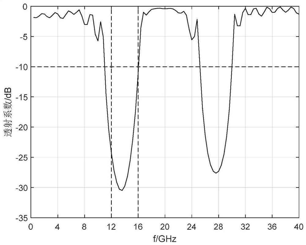
The invention relates to a method for designing a plasma photonic crystal structure, which comprises the following steps of: constructing a corresponding loss function according to the photonic band gap requirement of the plasma photonic crystal structure; constructing a plasma photonic crystal structure model, determining parameters and corresponding variation ranges of the plasma photonic crystal structure, and initializing a parameter vector formed by the parameters by adopting a particle swarm optimization method; substituting the initialization result into a calculation model corresponding to the plasma photonic crystal structure model, and calculating a transmission coefficient by using a finite difference time domain method to obtain a corresponding loss function value; iteratively updating the optimal parameter vector of the particles and the optimal parameter vector of the population through a particle swarm optimization method; and ending the optimization process of the particle swarm optimization method according to a preset iteration cut-off condition, and determining the plasma photonic crystal structure parameters meeting the photonic band gap requirements. The photonic band gap design of the plasma photonic crystal structure can be quickly realized.

Description

technical field [0001] The invention relates to the technical field of photonic crystals, in particular to a plasma photonic crystal structure design method, computer equipment and a computer-readable storage medium. Background technique [0002] Since the concept of photonic crystals was proposed, photonic crystals have attracted much attention due to their unique characteristics. Photonic crystals refer to artificial periodic dielectric structures with photonic band gap (Photonic Band-Gap, PBG for short) characteristics, and the so-called photonic band gap means that waves in a certain frequency range cannot propagate in this periodic dielectric structure, that is, This structure itself has a "forbidden band". The characteristics of photonic crystals mainly include: photonic bandgap characteristics, photon localization characteristics and optical characteristics. Among them, the photonic bandgap characteristic is one of the most interesting characteristics. The appearanc...

Claims


Application Information

Patent Timeline
Patent Type & Authority Applications(China)
IPC IPC(8): G06F30/23G06F30/27G06N3/00
CPCG06F30/23G06F30/27G06N3/006
Inventor 冯雪健邓浩川满良霍超颖韦笑殷红成
Owner BEIJING INST OF ENVIRONMENTAL FEATURES
Why Eureka
Try Eureka