Concrete building device suitable for linear steep tank flood overflow tank

A technology for concrete construction and flooding, which is applied in construction, measuring devices, lubrication indicating devices, etc., and can solve problems such as being easily mixed with a large amount of sediment

Active Publication Date: 2021-06-08
山东仁和天祥市政工程有限公司
View PDF7 Cites 0 Cited by
  • Summary
  • Abstract
  • Description
  • Claims
  • Application Information

AI Technical Summary

Problems solved by technology

[0004] The purpose of the present invention is to propose a concrete construction device suitable for straight steep groove spillways in order to solve the problem that river water is easily mixed with a large amount of sediment in the prior art

Method used


Image

  • Concrete building device suitable for linear steep tank flood overflow tank
  • Concrete building device suitable for linear steep tank flood overflow tank
  • Concrete building device suitable for linear steep tank flood overflow tank

Examples


Embodiment 1

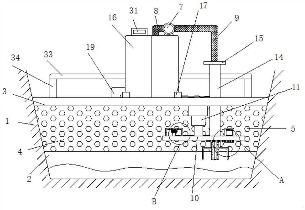
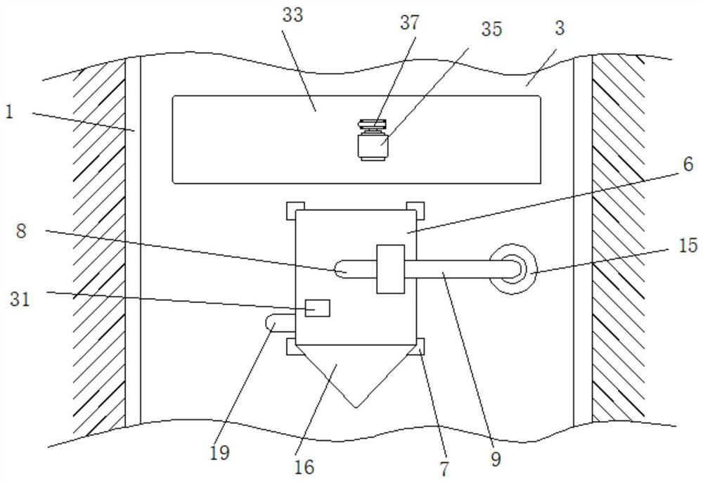
[0033] Embodiment one, such as Figure 1-9 As shown, a concrete construction device suitable for a straight-line steep trough spillway includes a spillway 1 whose cross-section is an inverted isosceles trapezoid. The bottom of the spillway 1 is provided with a sand storage tank 2. A fixed plate 3 is arranged horizontally above the tank 2, and both ends of the fixed plate 3 are respectively fixedly connected with the side wall of the overflow tank 1. The bottom surface of the fixed plate 3 is fixedly connected with an intercepting plate 4, and a plurality of filter holes 5 are uniformly arranged on the intercepting plate 4. The intercepting plate 4 is arranged vertically, the two ends of the intercepting plate 4 are in contact with the side wall of the overflow tank 1, the intercepting plate 4 is in contact with the side wall of the sand storage tank 2, the upper surface of the fixed plate 3 is equipped with a collection box 6, and the upper surface of the collection box 6 The ...

Embodiment 2

[0034]Embodiment two, such as Figure 1-3 , 5, a protective tube 14 is vertically arranged on the outer side of the telescopic tube 9, the protective tube 14 surrounds the telescopic tube 9, the protective tube 14 is fixedly connected with the upper surface of the connecting plate 10, and the protective tube 14 runs through the fixed plate 3 and connects with it Slidingly connected, the top of the protective tube 14 is fixedly connected with the limit ring 15, and the protective tube 14 protects the telescopic tube 9 to prevent the flowing animals in the river from damaging the telescopic tube 9.

Embodiment 3

[0035] Embodiment three, such as Figure 1-3 As shown, the side of the collection box 6 facing the upstream of the overflow tank 1 is fixedly connected with a drag reducing member 16. The drag reducing member 16 is in the shape of a triangular prism, and the collecting box 6 and the four corners are all provided with L-shaped fixing members 17. A plurality of fixing parts 17 are fixedly connected with the upper surface of the fixing plate 3, and a plurality of fixing parts 17 are in contact with the collection box 6, wherein two of the fixing parts 17 are in contact with the drag reducing parts 16, and the fixing parts 17 make the collection box 6 Installation and disassembly are simpler and more convenient.


PUM


Abstract

The invention discloses a concrete building device suitable for a linear steep tank flood overflow tank. The concrete building device comprises the flood overflow tank, wherein the section of the flood overflow tank is in an inverted isosceles trapezoid shape, a sand storage tank is arranged on the bottom face of the flood overflow tank, a fixing plate is horizontally arranged above the sand storage tank, the two ends of the fixing plate are fixedly connected with the side walls of the flood overflow tank, an intercepting plate is fixedly connected to the bottom face of the fixing plate, a plurality of filtering holes are evenly formed in the intercepting plate, the intercepting plate is vertically arranged, the two ends of the intercepting plate are in abutting contact with the side walls of the flood overflow tank, the intercepting plate is in abutting contact with the side walls of the sand storage tank, a collecting box is installed on the upper surface of the fixing plate, and a suction pump is fixedly connected to the upper surface of the collecting box. According to the concrete building device, the intercepting plate is arranged, sand and stone in river water are intercepted and filtered, then a suction pipe is used for suction recycling, the content of sediment in the river water is reduced, the water quality is improved, meanwhile, water and soil loss is reduced, environment protection is better facilitated, and the concrete building device is simple, practical, environmentally friendly and reliable.

Description

technical field [0001] The invention relates to the technical field of construction devices, in particular to a concrete construction device suitable for a linear steep groove spillway. Background technique [0002] Spill tanks are flood control equipment for water conservancy structures such as reservoirs. They are mostly built on one side of the dam, like a large tank. When the water level in the reservoir exceeds the safe limit, the water will flow downstream from the spill tank to prevent the dam from being destroyed. Including: inlet channel, control section, chute, outlet channel, used to vent the flood that cannot be accommodated by the planned reservoir, open type or overflow discharge structure with parapet inlet to ensure the safety of the dam body, spillway Generally, it does not work frequently, but it is an important building in the reservoir hub. The spillway is divided into normal spillway and extraordinary spillway according to the flood discharge standard an...

Claims


Application Information

Patent Timeline
IPC IPC(8): E02B3/10E02B7/26E02B7/36E02B8/02E02B8/06G01F23/00B02C18/10
CPCE02B3/10E02B7/26E02B7/36E02B8/023E02B8/06G01F23/00B02C18/10B02C18/0084B02C2201/06Y02A10/11
Inventor 邵烨
Owner 山东仁和天祥市政工程有限公司
Why Eureka
Try Eureka