Cutting device for steel pipe machining

A technology for cutting devices and steel pipes, applied in pipe shearing devices, shearing devices, metal processing, etc., can solve the problems of cutting finished products that do not meet the requirements, steel pipes that are easy to deviate from the position, time-consuming and labor-intensive failure of steel pipes, etc.

Active Publication Date: 2021-06-08
佛山市银天金属制品有限公司
View PDF9 Cites 1 Cited by
  • Summary
  • Abstract
  • Description
  • Claims
  • Application Information

AI Technical Summary

Problems solved by technology

[0003] However, the current cutting device used for steel pipe processing needs to cut one by one when cutting, which is time-consuming and laborious and cannot clamp the steel pipe. The steel pipe is easy to deviate from the position during cutting, and the cut product may not meet the requirements.

Method used


Image

  • Cutting device for steel pipe machining
  • Cutting device for steel pipe machining
  • Cutting device for steel pipe machining

Examples


Embodiment 1

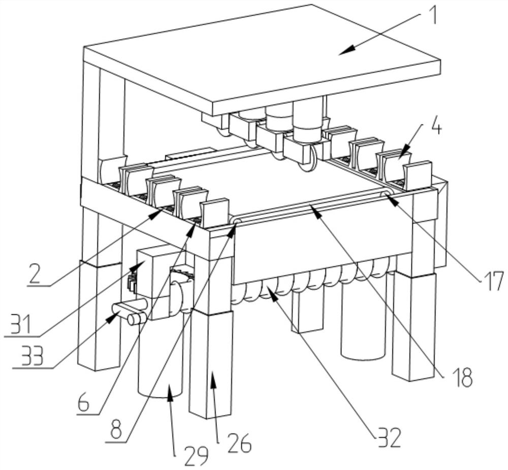
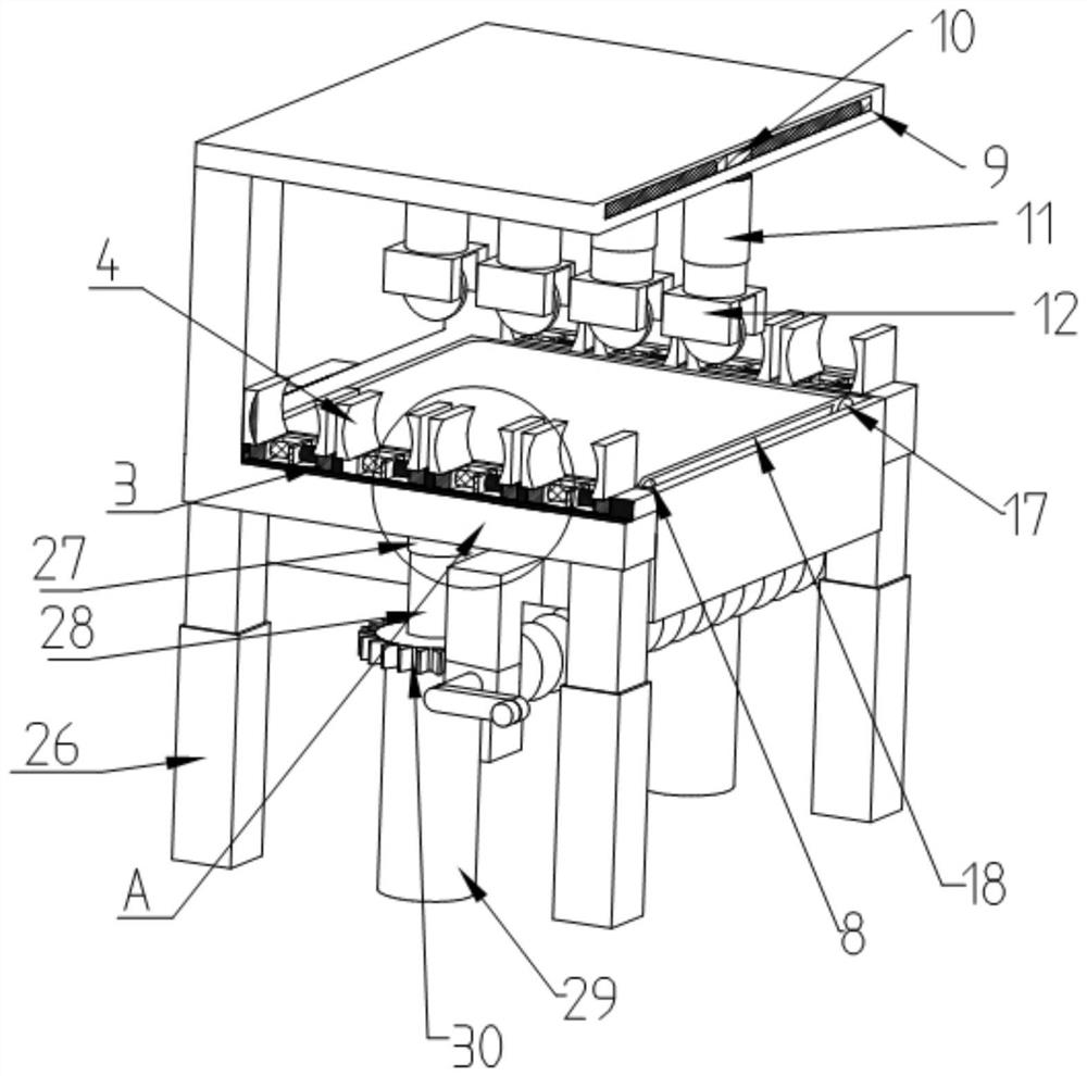
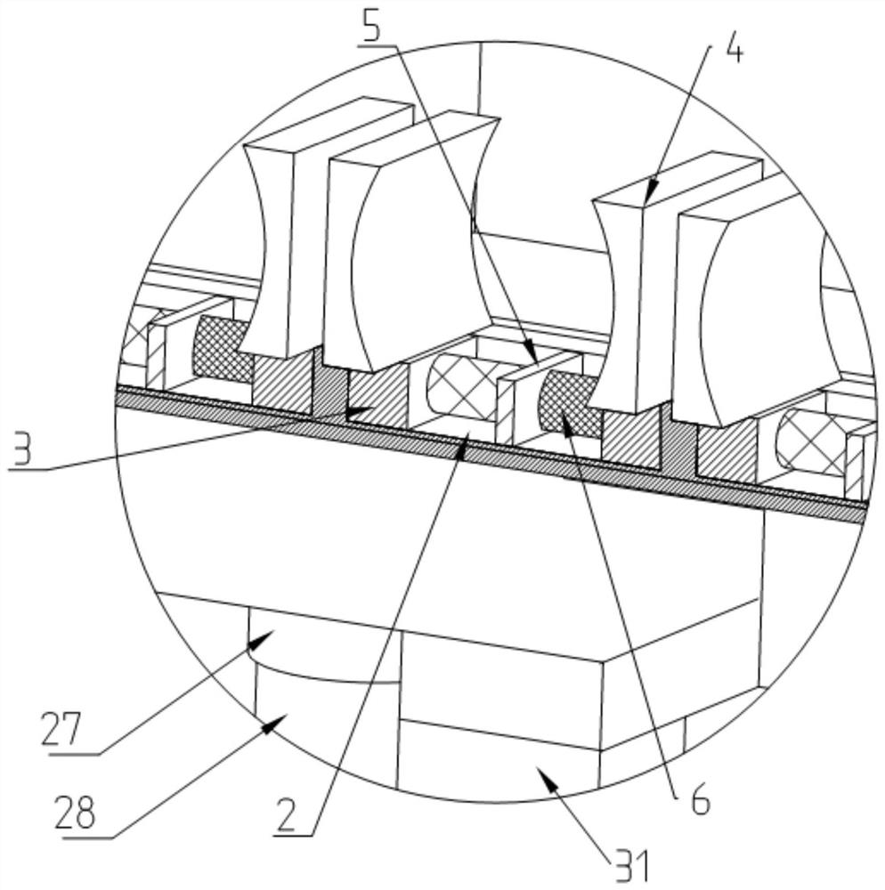
[0029] Such as Figure 1 to Figure 6 As shown, the present invention provides a cutting device for steel pipe processing, including a workbench 1, the left and right ends of the workbench 1 are respectively provided with first moving grooves 2, and the first moving grooves 2 are evenly distributed at the left and right ends of the workbench 1, The front and rear ends of the first moving groove 2 are respectively slidingly connected with a moving block 3, the upper end of the moving block 3 is fixedly connected with a clamping block 4, and the middle part of the first moving groove 2 is fixedly connected with a first fixed block at the middle of two adjacent clamping blocks 4. 5. The upper end of the first fixed block 5 located on the left side of the workbench 1 is equipped with a light emitting and receiving device and a solenoid valve. When the light emitting and receiving device is blocked by an object, when the light emitting and receiving device cannot receive the emitted ...

Embodiment 2

[0046] The applicant found that in the actual production process, steel pipes of different lengths are often required. In order to meet the diversified needs of actual production, the operation process of Example 1 was analyzed. The applicant found that in Example 1, the cut steel pipes The length of the steel pipe is (vt+l). If the rotation speed of the second motor 19 is changed, the transmission speed v of the conveyor belt 18 will also change accordingly. If v changes, (vt+l) will change, thus passing By controlling the transmission speed v, steel pipes with different cutting lengths will be obtained. Therefore, the applicant calculates the required speed v of the second motor 19 according to the required length of the steel pipe, and controls the second motor 19 to make the speed v, Therefore, the length of the steel pipe obtained by cutting is the required length, and the purpose of obtaining steel pipes with different cutting lengths through one instrument is realized. ...


PUM


Abstract

The invention belongs to the technical field of steel pipe machining and cutting, and discloses a cutting device for steel pipe machining. The cutting device comprises a worktable, wherein first moving grooves are formed in the left end and the right end of the worktable respectively, and the first moving grooves are uniformly distributed in the left end and the right end of the worktable; moving blocks are slidably connected to the front ends and the rear ends of the first moving grooves respectively, clamping blocks are fixedly connected to the upper ends of the moving blocks; first fixing blocks are fixedly connected to the middles of the first moving grooves; and light emitting and receiving devices and electromagnetic valves are arranged on he first fixing blocks. The light emitting and receiving devices and the electromagnetic valves are matched with each other, so that the purpose of clamping a steel pipe can be achieved. Meanwhile, automatic feeding and conveying of the steel pipe is achieved through the arrangement of a conveying belt. By adjusting the height of a lifting table, the conveying belt is prevented from being scratched when the cutting device cuts the steel pipe, and the conveying belt is prevented from being damaged by high temperature generated by cutting.

Description

technical field [0001] The invention belongs to the technical field of steel pipe processing and cutting, in particular to a cutting device for steel pipe processing. Background technique [0002] Steel pipe is a hollow long strip of round steel, which is widely used in petroleum, chemical, medical, food, light industry, mechanical instrumentation and other industrial pipelines and mechanical structural components, and is also widely used in the manufacture of mechanical parts and engineering structures , the steel pipes are generally longer in length, and for the convenience of use, the steel pipes are usually cut into small sections. [0003] However, the cutting devices used in the current steel pipe processing need to cut one by one during cutting, which is time-consuming and laborious and cannot clamp the steel pipes. The steel pipes are easy to deviate from the position during cutting, and the cut products may not meet the requirements. Contents of the invention [...

Claims


Application Information

Patent Timeline
Patent Type & Authority Applications(China)
IPC IPC(8): B23D21/00B23Q3/06B23Q7/00B23Q11/00
CPCB23D21/00B23Q3/064B23Q7/003B23Q11/0067
Inventor 常山亮
Owner 佛山市银天金属制品有限公司
Why Eureka
Try Eureka