
Energy-saving and environment-friendly plastic chemical production equipment

A technology for chemical production, energy saving and environmental protection, applied in the chemical industry, sustainable manufacturing/processing, chemical/physical/physical-chemical stationary reactors, etc. and other problems, to avoid the interruption of plastic processing, to avoid incomplete plastic processing, and to facilitate cleaning or replacement.

Active Publication Date: 2021-06-08
JIANGSU OCEAN UNIV
View PDF5 Cites 0 Cited by
  • Summary
  • Abstract
  • Description
  • Claims
  • Application Information

AI Technical Summary

Problems solved by technology

[0004] The existing plastic chemical production equipment usually does not have the function of graded processing, which will lead to low quality and uneven mixing of the produced plastic additives
Not only that, the general plastic chemical production equipment also has many problems such as low production efficiency and complex structure.

Method used


Image

  • Energy-saving and environment-friendly plastic chemical production equipment
  • Energy-saving and environment-friendly plastic chemical production equipment
  • Energy-saving and environment-friendly plastic chemical production equipment

Examples


Embodiment 1

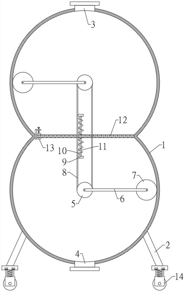
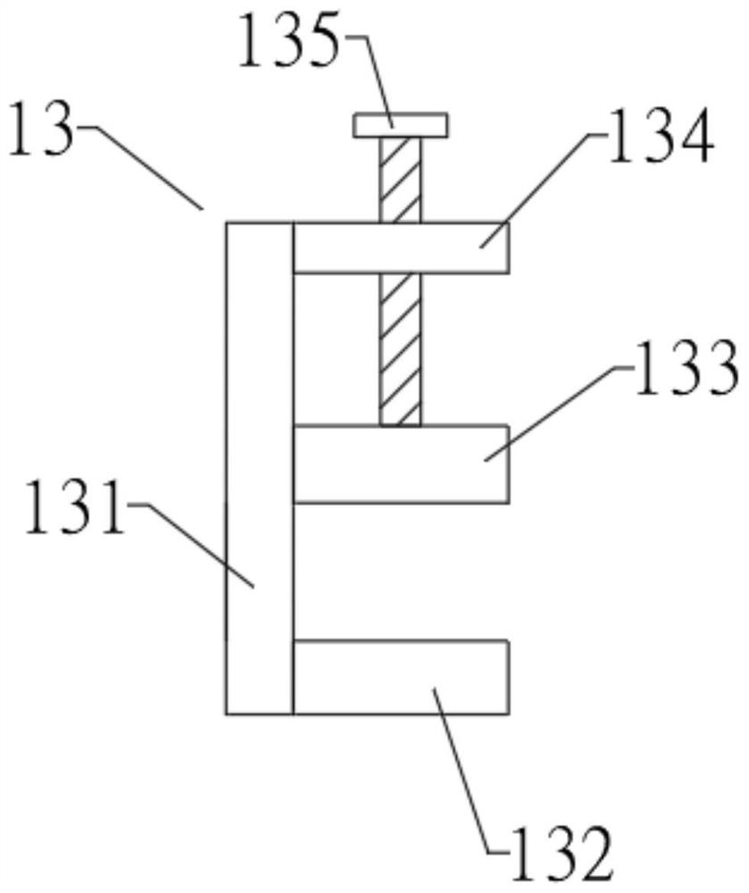
[0032] refer to Figure 1-3 , an energy-saving and environment-friendly plastic chemical production equipment, comprising a container 1, the container 1 adopts a gourd-shaped structure, a plurality of support feet 2 are fixedly connected to the outside of the bottom end of the container 1, and a buffer walking mechanism 14 is arranged on the bottom end of the support feet 2, Buffer walking mechanism 14 is made of top plate 141, pull bar 142, spring shock absorber 144, slotting 143, base 145 and road wheel 146. The top plate 141 is fixedly connected with the bottom end of the supporting foot 2, the top plate 141 is provided with a slot 143, the sliding wheel in the slot 143 is connected with a pull rod 142 adopting a T-shaped structure, and the end of the pull rod 142 away from the top plate 141 is fixedly connected with a base 145, A running wheel 146 is rotatably connected to the base 145 , and a spring shock absorber 144 is fixedly connected between the base 145 and the top ...

Embodiment 2

[0038] refer to Figure 4-5 , The difference between this embodiment and Embodiment 1 is that the connecting rod 6 adopts a telescopic connecting rod, and the telescopic connecting rod consists of a first rod body 61, a second rod body 62, a stopper 63, a sliding rod 64, a return spring 65, a first fixed plate 66 and the second fixed plate 67 constitute. The first rod body 61 is fixedly connected with the transmission wheel 5, the second rod body 62 is rotationally connected with the drum 7, the second rod body 62 is fixedly connected with the first fixed plate 66, and the second rod body 62 is vertically arranged with the first fixed plate 66, the first The rod body 61 is fixedly connected with a second fixed plate 67, and the first rod body 61 and the second fixed plate 67 are vertically arranged, and the second fixed plate 67 is fixedly connected with two sliding rods 64 symmetrically, and the sliding rod 64 is fixedly connected with a stopper 63 , the slide bar 64 is slid...


PUM


Abstract

The invention discloses energy-saving and environment-friendly plastic chemical production equipment, which comprises a container, the container is of a calabash-shaped structure, a plurality of supporting legs are fixedly connected to the outer side of the bottom end of the container, a clamping mechanism is arranged in the middle of the container, a horizontally-arranged screen plate is clamped on the clamping mechanism, and the interior of the container is divided into an upper space and a lower space by the screen plate. By arranging the screen plate, the interior of the container is divided into an upper space and a lower space by the screen plate, materials in the upper space can penetrate through the screen plate to fall into the lower space for further processing when the particle size is small after processing, and the problem that processing is uneven due to the fact that plastics with large particle difference are mixed together is solved.

Description

technical field [0001] The invention relates to the technical field of plastic chemical production equipment, in particular to an energy-saving and environment-friendly plastic chemical production equipment. Background technique [0002] Chemical equipment is a part of chemical machinery. Chemical machinery consists of two parts. One is chemical machinery, which mainly refers to equipment such as fans, compressors, and various pumps for fluid transportation. The main components are moving machinery, generally called chemical engineering. machine. The second is that chemical equipment mainly refers to machinery whose components are static, such as separation equipment such as towers, containers, reactor equipment, etc., sometimes also called non-standard equipment. The division between chemical machinery and other machinery is not very strict. For example, some pumps used in chemical processes are also general equipment used in other industrial sectors. Also in the chemical...

Claims


Application Information

Patent Timeline
IPC IPC(8): B01J19/18
CPCB01J19/18Y02P20/10
Inventor 徐国想王苏广陆俊臣
Owner JIANGSU OCEAN UNIV
Learn More