


Quick Research
Generate reliable direction feasibility study reports for your R&D in just a few steps.

Technical Q&A
Discover and master advanced knowledge NOW. Basics, ideas, possibilities, all at once.

Find Solutions
As an expert in R&D theories, this can generate solutions to your technical problems instantly.

Evaluate Feasibility
Analyze your overall solution with one click, know your potential R&D risks in advance.

Monitor Landscape
Get weekly tech updates, stay abreast of the latest tech innovations and key insights.
Connector assembly
A connector assembly and connector technology, which are applied in the direction of connection, parts of connecting devices, protective grounding/shielding devices of connecting parts, etc., can solve the problems of difficult processing of convex hulls, etc. Guaranteed effect of reliability
- Summary
- Abstract
- Description
- Claims
- Application Information
AI Technical Summary
Problems solved by technology
Method used
Image

Examples
specific Embodiment 1
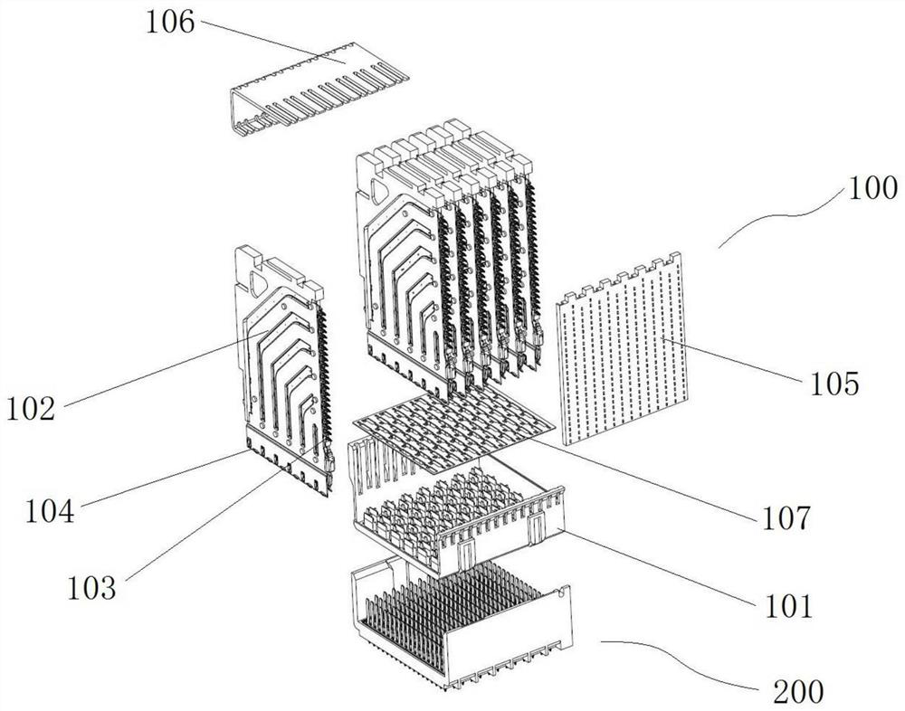
[0087] Such as figure 1 As shown, the connector assembly includes a mutually interpolated female terminal connector 100 and a male terminal connector 200, whether the female terminal connector 100 or the male terminal connector 200, is used as a front end for one end of the insertion. . The connector of the present embodiment is a male terminal connector 200.
[0088] The female terminal connector 100 includes a female terminal casing 101 and a plurality of terminal modules 102 disposed on the female end housing 101, wherein the terminal module 102 has a mounting end 103 and a mating end 104, and the mounting end 103 is used to fix the installation. On the board, the mating end 104 is used to interpolate with the male connector 200. The terminal module 102 is integrally a square plate body, and each terminal module 102 is sequentially arranged in the thickness direction of the terminal module 102.
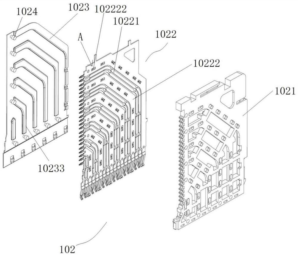
[0089] The structure of the terminal module 102 is like Figures 2 to 10 As shown, ...
specific Embodiment 2
[0118] Such as Figure 29 to 32 As shown, the difference from Example 1 is in that in Example 1, the guide slope is an inclined plane. In this embodiment, the guide slope is a curved surface 10238 in the shield plate 1023, and the window 10237 between the bolt packet 10232 and the body portion 10231, the shield plate 1023 is not connected by the rivet 1024 and the ground terminal 10222.
Embodiment 1
[0120] In Examples 1 and Example 2, the bumps were all integrally stamped, and there was a gap between the rear end of the bump and the main body portion. In the present embodiment, there is a gap between the front end or the left and right ends and the left and right ends, that is, at least one end has a gap.
PUM
 Abstract
Description
Claims
Application Information
 - R&D Engineer
- R&D Manager
- IP Professional
- Industry Leading Data Capabilities
- Powerful AI technology
- Patent DNA Extraction
Browse by: Latest US Patents, China's latest patents, Technical Efficacy Thesaurus, Application Domain, Technology Topic, Popular Technical Reports.
© 2024 PatSnap. All rights reserved.Legal|Privacy policy|Modern Slavery Act Transparency Statement|Sitemap|About US| Contact US: help@patsnap.com