
Light strip refinement method for linear laser skin opposite seam measurement

A line laser and light strip technology, applied in the field of image processing, can solve the problems of fuzzy key features of the image and the inability to accurately extract the center of light strips, etc., to achieve the effects of preserving integrity, improving anti-noise ability, and accelerating the iterative process

Pending Publication Date: 2021-06-04
NANJING UNIV OF AERONAUTICS & ASTRONAUTICS +1
View PDF0 Cites 0 Cited by
  • Summary
  • Abstract
  • Description
  • Claims
  • Application Information

AI Technical Summary

Problems solved by technology

[0003] At present, there are two problems in light strip thinning: First, most image denoising methods generally directly perform correlation operations on the original image in the spatial domain, and then change the gray value of some pixels disturbed by noise to achieve image filtering effect , but these methods all cause the key features of the image to be blurred; second, the commonly used methods for extracting the center of the structured light strip, such as the center of gravity method, the extremum method, and the Hessian matrix method, are all based on the near-Gaussian distribution of the cross-sectional energy of the light strip. With the improvement of the quality of the line laser hardware itself, the energy distribution of the cross-section of the light bar projected by the laser has shown a non-Gaussian distribution at present, and it is impossible to accurately extract the center of the light bar by continuing to use the traditional method of extracting the center of the light bar.

Method used


Image

  • Light strip refinement method for linear laser skin opposite seam measurement
  • Light strip refinement method for linear laser skin opposite seam measurement
  • Light strip refinement method for linear laser skin opposite seam measurement

Examples


Embodiment Construction

[0046] The technical solution of this patent will be further described in detail below in conjunction with specific embodiments.

[0047] In the description of this patent, it should be noted that, unless otherwise clearly specified and limited, the terms "installation", "connection", "connection", and "setting" should be understood in a broad sense, for example, it can be fixed connection, setting , can also be detachably connected and set, or integrally connected and set. Those of ordinary skill in the art can understand the specific meanings of the above terms in this patent according to specific situations.

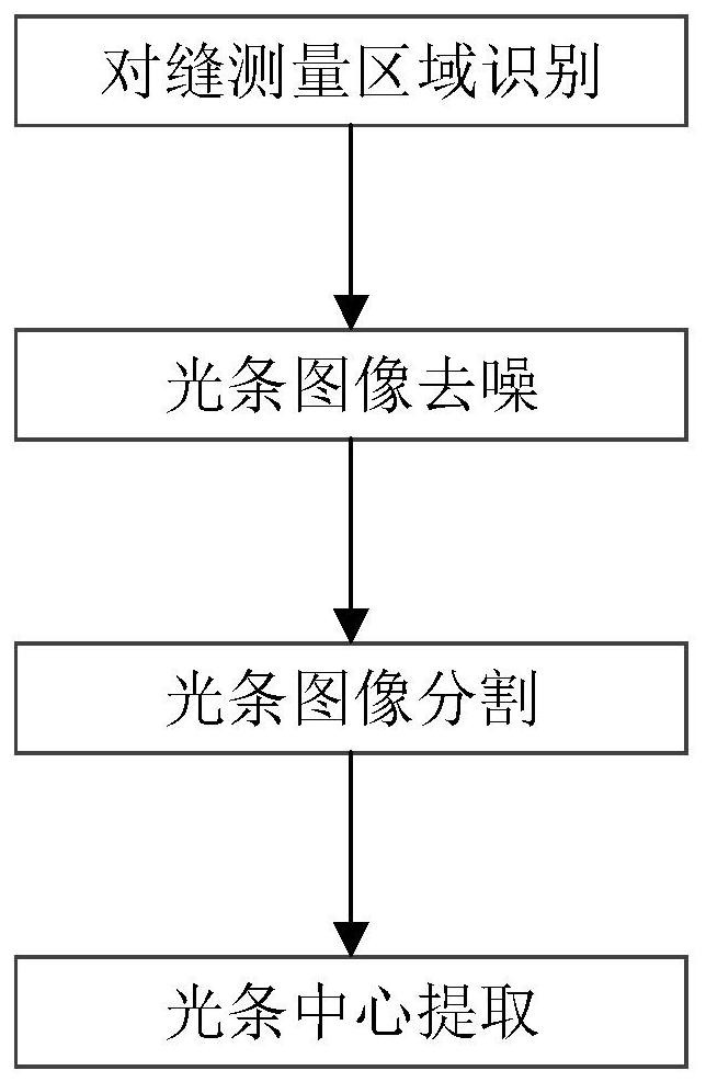
[0048] A light strip thinning method for line laser skin to seam measurement, comprising the following steps:

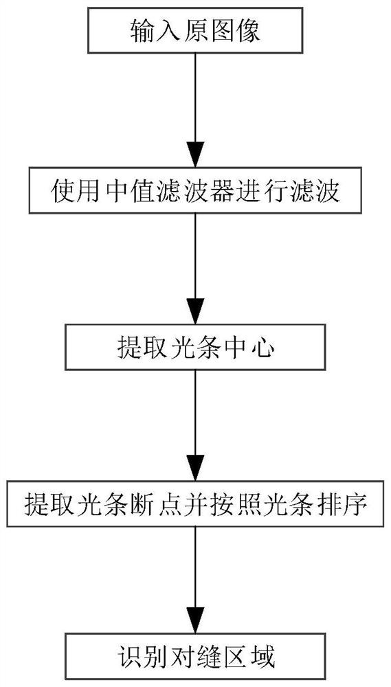
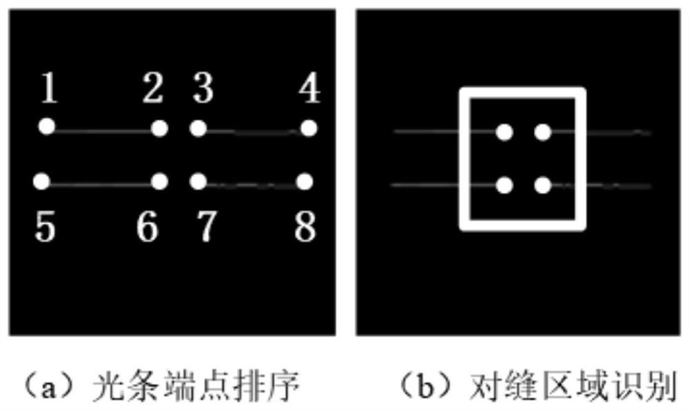
[0049] S1: Identify the gap measurement area according to the serial number of the end point of the light bar;

[0050]S2: Identify the skin butt seam area based on the end point of the light bar;

[0051] S3: Using an adaptive full variational filter fun...


PUM


Abstract

The invention discloses a light stripe refining method for linear laser skin opposite seam measurement, and relates to the technical field of image processing. Comprising the following steps: recognizing an opposite seam measurement region according to a light bar endpoint sequence number; removing light stripe image noise from the recognized opposite seam measurement region image by adopting a self-adaptive total variation filtering function; segmenting the light strip image by adopting an improved fuzzy C-means method, and separating the light strip from the original image; and extracting the center of the light bar by adopting a method based on a skeleton extraction template and a regional gray gravity center, and obtaining the center pixel coordinate of the skin surface line laser light bar. The method has the advantages that 1) the opposite seam measurement region is quickly recognized, and the subsequent image processing efficiency is improved; 2) Gaussian noise and salt and pepper noise in the light strip image can be significantly removed, and the signal-to-noise ratio of the image is effectively improved; and 3) the anti-interference performance of the light bar segmentation method on image noise is improved through the optimized fuzzy C-means algorithm.

Description

technical field [0001] The invention relates to the technical field of image processing, in particular to a thinning method of light stripes for line laser skin to seam measurement. Background technique [0002] The line laser emitter projects structured light, which interferes with the seam of the skin, and the image sensor collects the light strip image, and the 2D structured light shape at the seam of the skin reflects the 3D contour information of the step difference and the gap at the seam. In this process, the image sensor itself and the external lighting environment will interfere with the skin measurement image, making the image acquisition results contain noise, of which Gaussian noise and salt and pepper noise are the main ones. Therefore, the structured light measurement of aircraft skin to seam Image processing and light strip feature extraction affect the accuracy and reliability of the entire gap measurement system. [0003] At present, there are two problems ...

Claims


Application Information

Patent Timeline
Patent Type & Authority Applications(China)
IPC IPC(8): G06K9/44G06K9/40G06K9/46
CPCG06V10/34G06V10/30G06V10/44
Inventor 李泷杲黄翔李根鲁小翔楼佩煌钱晓明陶克梅王静波
Owner NANJING UNIV OF AERONAUTICS & ASTRONAUTICS
Learn More