Drainage pipeline flow limiting adjusting device

The technology of a regulating device and a drainage pipeline is applied in the field of water supply and drainage, which can solve the problems of high cost, difficult assembly, complicated structure of the regulating valve, etc., and achieve the effect of reducing engineering cost and low manufacturing cost.

Active Publication Date: 2021-06-04
DALIAN STAR TECH CO LTD
View PDF6 Cites 1 Cited by
  • Summary
  • Abstract
  • Description
  • Claims
  • Application Information

AI Technical Summary

Problems solved by technology

[0003] In order to solve the problems in the background technology that the regulating valve installed on a large drainage pipe is complex in structure, difficult to assemble, and has a high cost, the present invention proposes a drainage pipe flow-limiting regulating device

Method used


Image

  • Drainage pipeline flow limiting adjusting device
  • Drainage pipeline flow limiting adjusting device
  • Drainage pipeline flow limiting adjusting device

Examples


Embodiment 1

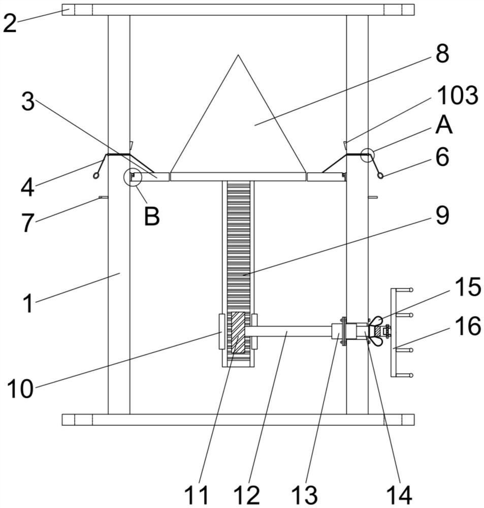
[0026] Embodiment 1: a kind of drain pipe flow limiting adjustment device, such as figure 1 As shown, including the steel pipe 1, the upper and lower ends of the steel pipe 1 are welded with flange plates 2, the interior of the steel pipe 1 is provided with an annular baffle 3, the baffle 3 and the inner wall of the steel pipe 1 are perpendicular to each other, and the middle of the annular baffle 3 Form water holes.

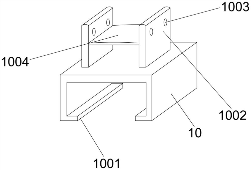
[0027] Such as Figure 6 As shown, the annular baffle plate 3 is mainly composed of four arc-shaped plates of the same size. In order to facilitate the installation of each component, the steel pipe 1 itself can be finally welded by using four arc-shaped steel plates (the number of arc-shaped steel plates is preferably the same as The number of arc-shaped plates is the same), and an arc-shaped plate is installed on each arc-shaped steel plate.

[0028] The wall of the steel pipe 1 is provided with a wire hole 102 for the steel wire 4 to pass through, such as ...

Embodiment 2

[0039] Embodiment 2: A drainage pipe current limiting adjustment device, including a steel pipe 1, the upper and lower ends of the steel pipe 1 are welded with flange plates 2, the interior of the steel pipe 1 is provided with an annular baffle 3, the baffle 3 and the steel pipe 1 The inner walls are perpendicular to each other, and the middle part of the annular baffle plate 3 forms a water hole. The annular baffle plate 3 is a whole annular plate, and the annular baffle plate 3 is welded to the inner wall of the steel pipe 1 .

Embodiment 3

[0040] Embodiment 3: a kind of drain pipe current limiting adjustment device, such as figure 1 As shown, including the steel pipe 1, the upper and lower ends of the steel pipe 1 are welded with flange plates 2, the interior of the steel pipe 1 is provided with an annular baffle 3, the baffle 3 and the inner wall of the steel pipe 1 are perpendicular to each other, and the middle of the annular baffle 3 Form water holes. Such as Figure 6 As shown, the annular baffle plate 3 is mainly composed of four arc-shaped plates of the same size. In order to facilitate the installation of each component, the steel pipe 1 itself can be finally welded by using four arc-shaped steel plates (the number of arc-shaped steel plates is preferably the same as The number of arc-shaped plates is the same), and an arc-shaped plate is installed on each arc-shaped steel plate.

[0041] The wall of the steel pipe 1 is provided with a wire hole 102 for the steel wire 4 to pass through, such as Figur...


PUM


Abstract

The invention provides a drainage pipeline flow limiting adjusting device. The problems that an adjusting valve installed on a large drainage pipeline is complex in structure, consequently, assembling is not easy, and the manufacturing cost is high are solved. The drainage pipeline flow limiting adjusting device comprises a steel pipe; flange plates are fixedly arranged at the upper end and the lower end of the steel pipe; an annular baffle is arranged in the steel pipe and is perpendicular to the inner wall of the steel pipe; a water flowing hole is formed in the middle portion of the annular baffle; a cone capable of moving up and down is arranged in the water flowing hole; the diameter of the bottom of the cone is equal to the inner diameter of the water flowing hole; a vertical tooth plate is arranged at the bottom of the cone; a sliding way component is arranged on the inner wall of the cone; the tooth plate is inserted in a sliding way clamping plate of the sliding way component in a sliding manner; the sliding way clamping plate is of a frame type plate structure with a front opening; a limiting plate preventing the tooth plate from disengaging is arranged at the front portion of the sliding way clamping plate; a gear engaged with the tooth plate is arranged in the steel pipe; the middle portion of the gear is connected with a transversely-arranged shaft rod component; and a shaft hole is formed in the wall body of the lower portion of the steel pipe, and the other end of the shaft rod component penetrates out of the shaft hole to be connected with a hand wheel.

Description

technical field [0001] The invention relates to the technical field of water supply and drainage, in particular to a flow-limiting regulating device for a drainage pipe. Background technique [0002] Water conservancy projects are projects built to control and allocate natural surface water and groundwater to achieve the purpose of eliminating harm and rejuvenating profits. Also known as water engineering. Water is an indispensable precious resource for human production and life, but its natural state does not fully meet human needs. Only by building water conservancy projects can we control water flow, prevent floods, and regulate and distribute water to meet the needs of people's life and production for water resources. Water conservancy projects need to build different types of hydraulic structures such as dams, dikes, spillways, sluices, water inlets, channels, canals, rafts, and fishways to achieve their goals. In water conservancy projects, regulating valves are oft...

Claims


Application Information

Patent Timeline
Patent Type & Authority Applications(China)
IPC IPC(8): E03F3/04E03F7/00
CPCE03F3/04E03F7/00
Inventor 赵忠爱张一张彦强
Owner DALIAN STAR TECH CO LTD
Why Eureka
Try Eureka