Tubular electric arc ablation device and ablation method
An arc ablation and tubular technology, which is applied in the direction of electric heating devices, electrical components, heating by discharge, etc., can solve the problems that cannot meet the requirements of ablation test, ablation, burn-through and water leakage of the inner shell of the rear electrode, and achieve simple structure, Good economy, easy operation and maintenance
- Summary
- Abstract
- Description
- Claims
- Application Information
AI Technical Summary
Problems solved by technology
Method used
Image

Examples
Embodiment 1
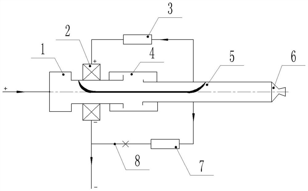
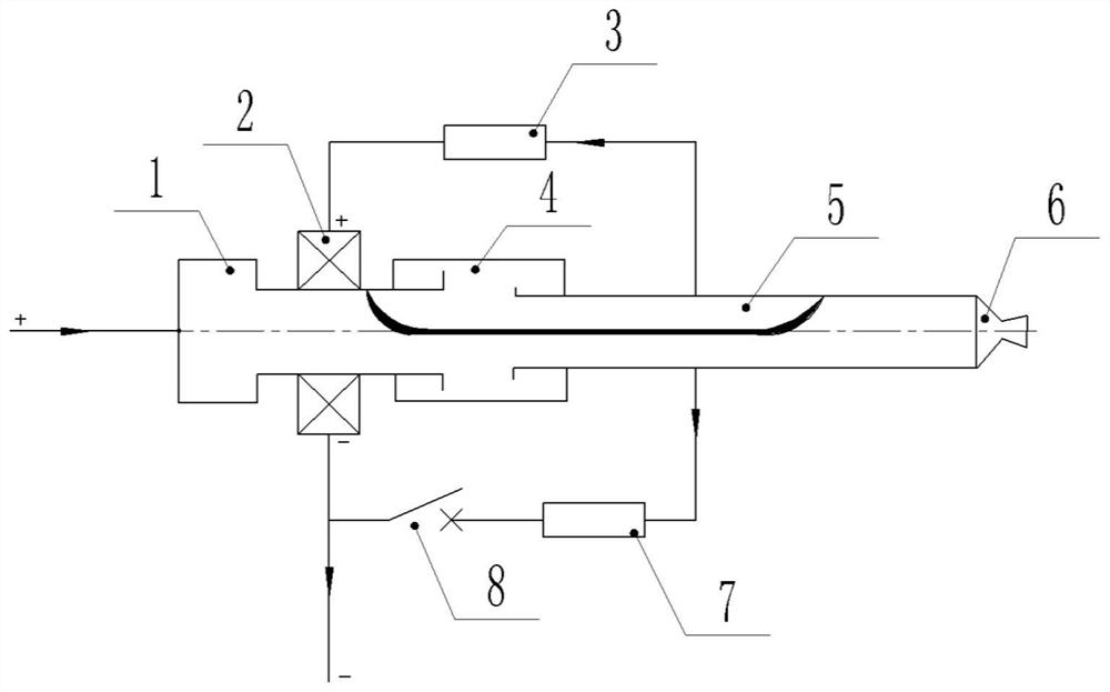
[0030] combine figure 1 with figure 2 As shown, the tubular arc ablation device of this embodiment includes a rear electrode 1, a rear electrode magnetic field coil 2, an air intake chamber 4, a front electrode 5, a nozzle 6 and a control unit, and the front electrode 5 and the rear electrode 1 are respectively arranged on The front end and rear end of the air intake chamber 4, the nozzle 6 is arranged at the front end of the front electrode 5, the rear electrode magnetic field coil 2 is set outside the rear electrode 1, the control unit is connected with the rear electrode magnetic field coil 2, and the control unit can adjust the rear electrode The magnetic field strength of the magnetic field coil 2 is used to change the arc root position at the rear electrode 1 .
[0031] In the tubular arc ablation device of the present embodiment, the air inlet chamber 4 has an air inlet for passing in a working gas (generally air); the front electrode 5 and the rear electrode 1 are bo...
Embodiment 2
[0044] This embodiment is improved on the basis of the tubular arc ablation device in Embodiment 1.
[0045] Specifically, combined with figure 1 with figure 2 As shown, the tubular arc ablation device of this embodiment also includes a front electrode magnetic field coil (not shown), the front electrode magnetic field coil is sleeved outside the front electrode 5, the control unit is connected with the front electrode magnetic field coil, and the control unit can adjust the front electrode magnetic field coil. The magnetic field strength of the electrode magnetic field coil is used to change the arc root position at the front electrode 5 .
[0046] In this embodiment, the setting method of the regulating unit for regulating the magnetic field strength of the front electrode magnetic field coil can be with reference to the regulating method for the rear electrode magnetic field coil 2; at this time, the regulating unit can also include a third resistor and a fourth resistor ...
Embodiment 3
[0049] This embodiment provides an ablation method, which is carried out by using the tubular arc ablation device of Embodiment 1. The ablation method includes the following steps:
[0050] A) Passing working gas into the air inlet chamber 4, and applying current to the tubular arc ablation device at the same time, the arc generated between the rear electrode 1 and the front electrode 5 heats the working gas to form a flow field to ablate the model;
[0051] B) After ablation for a period of time, adjust the magnetic field strength of the rear electrode magnetic field coil 2 through the control unit to change the arc root position at the rear electrode 1 .
[0052] When performing the ablation test, a certain current (usually 500-2000A) is applied to the tubular arc ablation device after the working gas (usually air) is introduced into the air inlet chamber 4, and the arc is generated on the rear electrode 1 and the front electrode. 5 and sprayed out through the nozzle 6 to fo...
PUM
 Abstract
Description
Claims
Application Information
 - R&D
- Intellectual Property
- Life Sciences
- Materials
- Tech Scout
- Unparalleled Data Quality
- Higher Quality Content
- 60% Fewer Hallucinations
Browse by: Latest US Patents, China's latest patents, Technical Efficacy Thesaurus, Application Domain, Technology Topic, Popular Technical Reports.
© 2025 PatSnap. All rights reserved.Legal|Privacy policy|Modern Slavery Act Transparency Statement|Sitemap|About US| Contact US: help@patsnap.com