
Camera module, electronic equipment, camera module control method and control device

A camera module and camera technology, applied to color TV parts, TV system parts, TVs, etc., can solve the problems of camera rotation anti-shake resistance and poor camera anti-shake effect, and achieve the effect of avoiding resistance

Active Publication Date: 2022-02-25
VIVO MOBILE COMM CO LTD
View PDF10 Cites 0 Cited by
  • Summary
  • Abstract
  • Description
  • Claims
  • Application Information

AI Technical Summary

Problems solved by technology

[0004] The purpose of the embodiment of the present application is to provide a camera module, which can solve the problem that the anti-shake effect of the camera is not good due to the large resistance to the rotation of the camera

Method used


Image

  • Camera module, electronic equipment, camera module control method and control device
  • Camera module, electronic equipment, camera module control method and control device
  • Camera module, electronic equipment, camera module control method and control device

Examples


Embodiment Construction

[0036] The following will clearly and completely describe the technical solutions in the embodiments of the present application with reference to the drawings in the embodiments of the present application. Obviously, the described embodiments are part of the embodiments of the present application, not all of them. Based on the embodiments in this application, all other embodiments obtained by persons of ordinary skill in the art without creative efforts fall within the protection scope of this application.

[0037] The terms "first", "second" and the like in the specification and claims of the present application are used to distinguish similar objects, and are not used to describe a specific sequence or sequence. It should be understood that the terms so used are interchangeable under appropriate circumstances such that the embodiments of the application can be practiced in sequences other than those illustrated or described herein, and that references to "first," "second," et...


PUM


Abstract

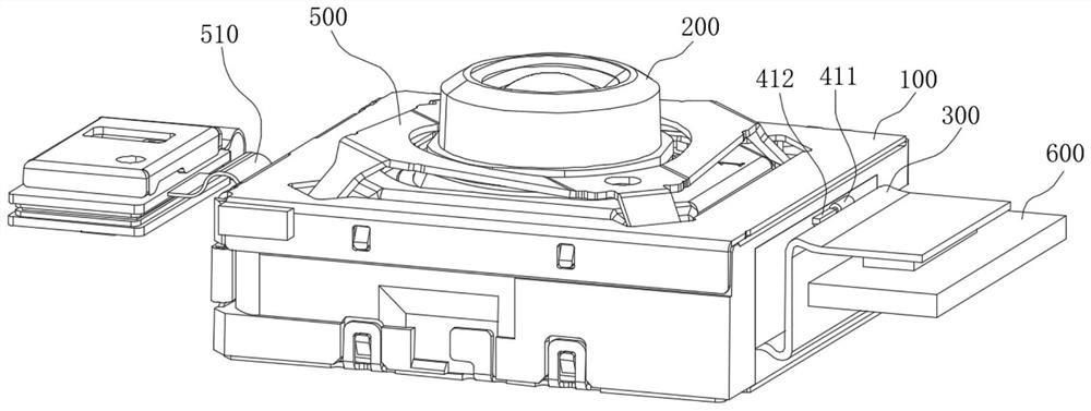
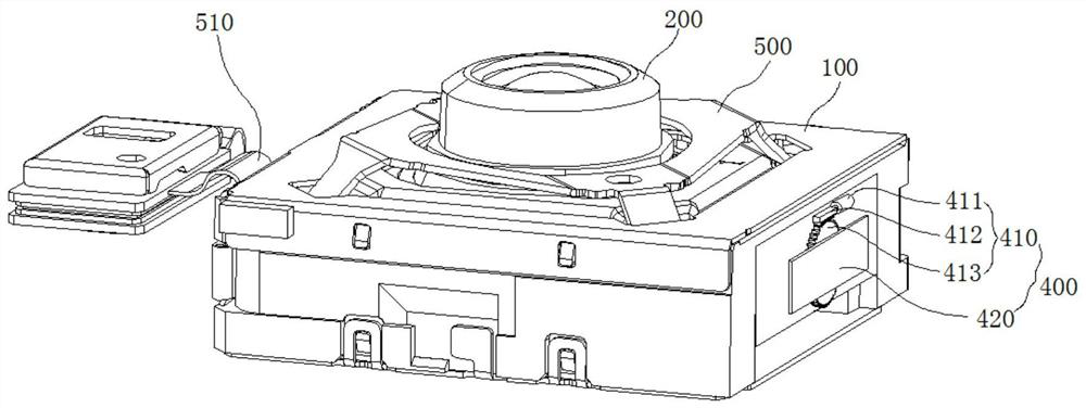
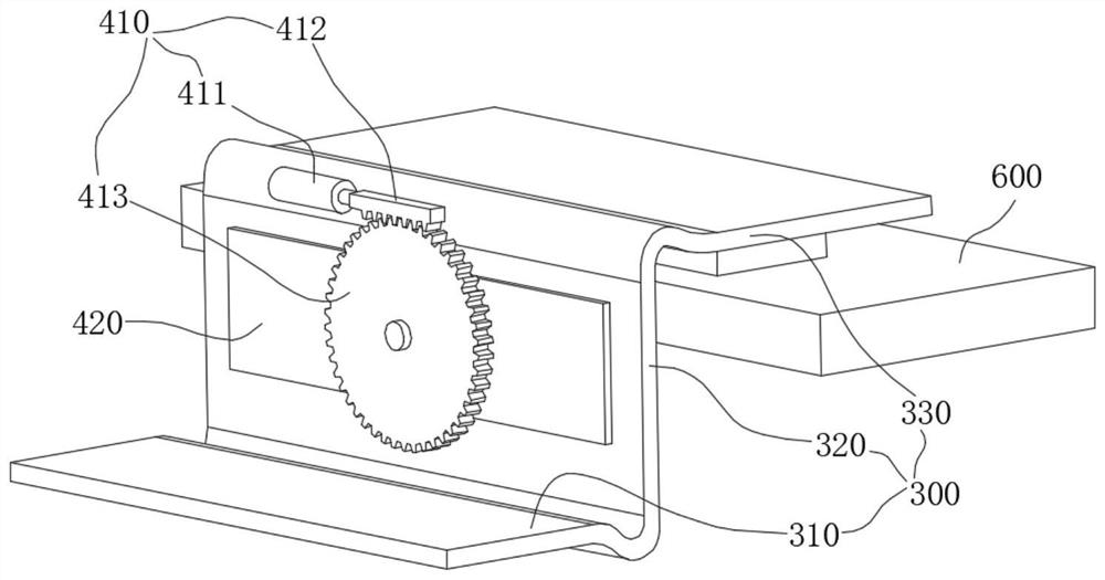
The application discloses a camera module, electronic equipment, a control method and a control device for the camera module, and belongs to the technical field of camera equipment. The camera module includes a camera bracket, a camera, a first flexible electrical connector and an adjustment mechanism. The camera is arranged on the camera bracket, and the camera can rotate around the first axis relative to the camera bracket. The adjustment mechanism includes a driving body and a supporting part, the driving body is arranged on the camera bracket, and the supporting part is connected with the driving body through transmission. The first flexible electrical connector includes a first segment and a second segment, and the second segment is fixedly connected with the supporting member. The first section is located between the support and the camera, and one end of the first section is electrically connected to the camera, and the other end of the first section is connected to the second section; the driving body drives the support to drive the first section and the second section around the second section. The axis rotates, and the second axis is collinear or parallel to the first axis. This solution can solve the problem that the anti-shake effect of the camera is not good due to the large resistance to the rotation and anti-shake of the camera.

Description

technical field [0001] The application belongs to the technical field of camera equipment, and in particular relates to a camera module. Background technique [0002] With the improvement of user demands, electronic devices have more and more functions. At present, more and more electronic devices have added an anti-shake function. In related technologies, in order to realize the anti-shake function, the electronic device is equipped with an anti-shake pan-tilt bracket, and a camera of the electronic equipment is movably arranged on the anti-shake pan-tilt bracket. During the specific shooting process, the camera can rotate relative to the anti-shake gimbal support, thereby realizing angle compensation and avoiding angle deviation caused by shaking. [0003] We know that the camera needs power to work. The camera is usually electrically connected to a power device (such as a motherboard) by using a flexible electrical connector (such as a flexible circuit board). However...

Claims


Application Information

Patent Timeline
Patent Type & Authority Patents(China)
IPC IPC(8): H04N5/225H04N5/232
CPCH04N23/50H04N23/687
Inventor 刘崇蒙张博
Owner VIVO MOBILE COMM CO LTD
Learn More