Broadband injection-locked frequency divider

A technology of injection locking and frequency divider, which is applied in the direction of power oscillators and electrical components, can solve the problems of large DC current and increased DC power consumption, etc., to expand bandwidth, reduce power supply voltage and DC power consumption, and reduce threshold The effect of voltage

Active Publication Date: 2021-06-01
XIDIAN UNIV
View PDF10 Cites 0 Cited by
  • Summary
  • Abstract
  • Description
  • Claims
  • Application Information

AI Technical Summary

Problems solved by technology

Although the circuit can expand the self-resonant frequency range through the variable capacitor array, but because it uses the traditional cross-coupled oscillator structure and multiple variable capacitors, it needs a large DC current to maintain the circuit oscillation, which increases the DC power. consumption

Method used


Image

  • Broadband injection-locked frequency divider
  • Broadband injection-locked frequency divider
  • Broadband injection-locked frequency divider

Examples


Embodiment Construction

[0023] The embodiments and effects of the present invention will be further described in detail below in conjunction with the accompanying drawings.

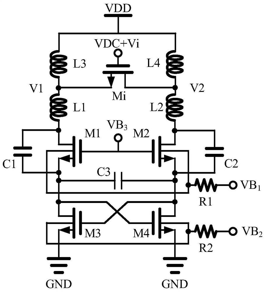
[0024] refer to figure 2 , the present invention includes injection transistor Mi, LC resonant cavity, Colpitts oscillator, switched current source and substrate bias circuit; injection transistor Mi is connected between the positive and negative signal output terminals of Colpitts oscillator, and LC resonant cavity is connected Between the power supply voltage VDD and the signal output terminal of the Colpitts oscillator, a switching current source is connected between the Colpitts oscillator and the power ground GND to generate alternate conduction tail currents. Both the Colpitts oscillator and the switching current source are connected to the substrate The bias circuit is used to reduce the threshold voltage of the transistor and reduce the DC power consumption of the circuit.

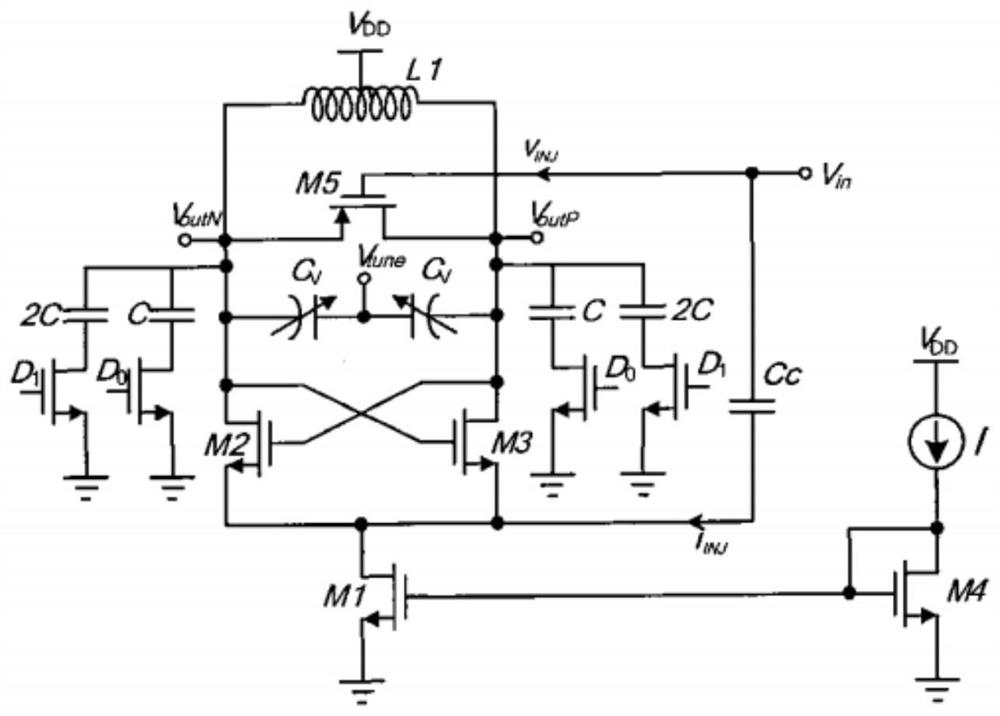
[0025] refer to image 3 , the circuit stru...


PUM


Abstract

The invention discloses a broadband injection locking frequency divider, which mainly solves the problems of narrow locking range and high power consumption in the prior art. The circuit comprises an inductance-capacitance resonant cavity, an injection transistor, a Colpitts oscillator and a switch current source. The oscillator is formed by connecting a transistor M1, a transistor M2, three capacitors and two inductors, the three capacitors form a positive feedback structure, and the two inductors isolate the positive feedback structure from the signal output end of the oscillator; the switch current source is formed by connecting a transistor M3 and a transistor M4, the transistor M3 and the transistor M4 are connected with a transistor M1 and a transistor M2 in the Colpitts oscillator so as to provide alternating conduction direct current for the Colpitts oscillator, and the Colpitts oscillator and the switch current source are both connected with a substrate biasing circuit so as to reduce power supply voltage. While the chip area is not increased, the frequency locking range of the frequency divider is widened, the direct current power consumption of the frequency divider is reduced, and the frequency divider can be applied to a chip of a radio frequency transceiver.

Description

technical field [0001] The invention belongs to the technical field of electronic circuits, and in particular relates to a broadband injection-locked frequency divider, which can be used in radio frequency transceiver chips for computers, wireless communications, radars, and smart homes. Background technique [0002] With the rise of multi-standard multi-band communication systems, wideband transceiver chips have attracted great attention. The phase-locked loop is one of the most important parts in the modern wireless communication system, and the frequency divider is an indispensable module in the phase-locked loop, so the frequency divider with wide locking range LR, low power consumption and small size has been developed , is of great significance. The LC injection-locked frequency divider based on the cross-coupled oscillator topology has been extensively studied due to its easy implementation and low power consumption. However, this injection-locked frequency divider u...

Claims


Application Information

Patent Timeline
IPC IPC(8): H03B5/04H03B5/12
CPCH03B5/04H03B5/12
Inventor 李振荣张新雨李臻余立艳庄奕琪
Owner XIDIAN UNIV
Why Eureka
Try Eureka