Rapid heat dissipation shell for outdoor laser

A heat dissipation shell and laser technology, applied in the field of lasers, can solve problems such as difficulty in keeping the shell clean, lack of automatic cleaning, and reduced shell efficiency, so as to achieve the effects of improving heat dissipation, cleaning effect, and heat dissipation rate

Pending Publication Date: 2021-06-01
伍章明
View PDF0 Cites 0 Cited by
  • Summary
  • Abstract
  • Description
  • Claims
  • Application Information

AI Technical Summary

Problems solved by technology

[0003] At the same time, for lasers used outdoors, because the dust and impurities outdoors are more serious than indoors, when dust or impurities are attached to the laser shell, it will greatly reduce the heat dissipation efficiency of the shell to the air, so the laser used outdoors , try to avoid dust on the shell
The existing laser casing does not have the effect of automatic cleaning, so it is difficult to keep the casing clean for a long time, and manual cleaning is required, which is laborious and laborious

Method used


Image

  • Rapid heat dissipation shell for outdoor laser
  • Rapid heat dissipation shell for outdoor laser
  • Rapid heat dissipation shell for outdoor laser

Examples


Embodiment 1

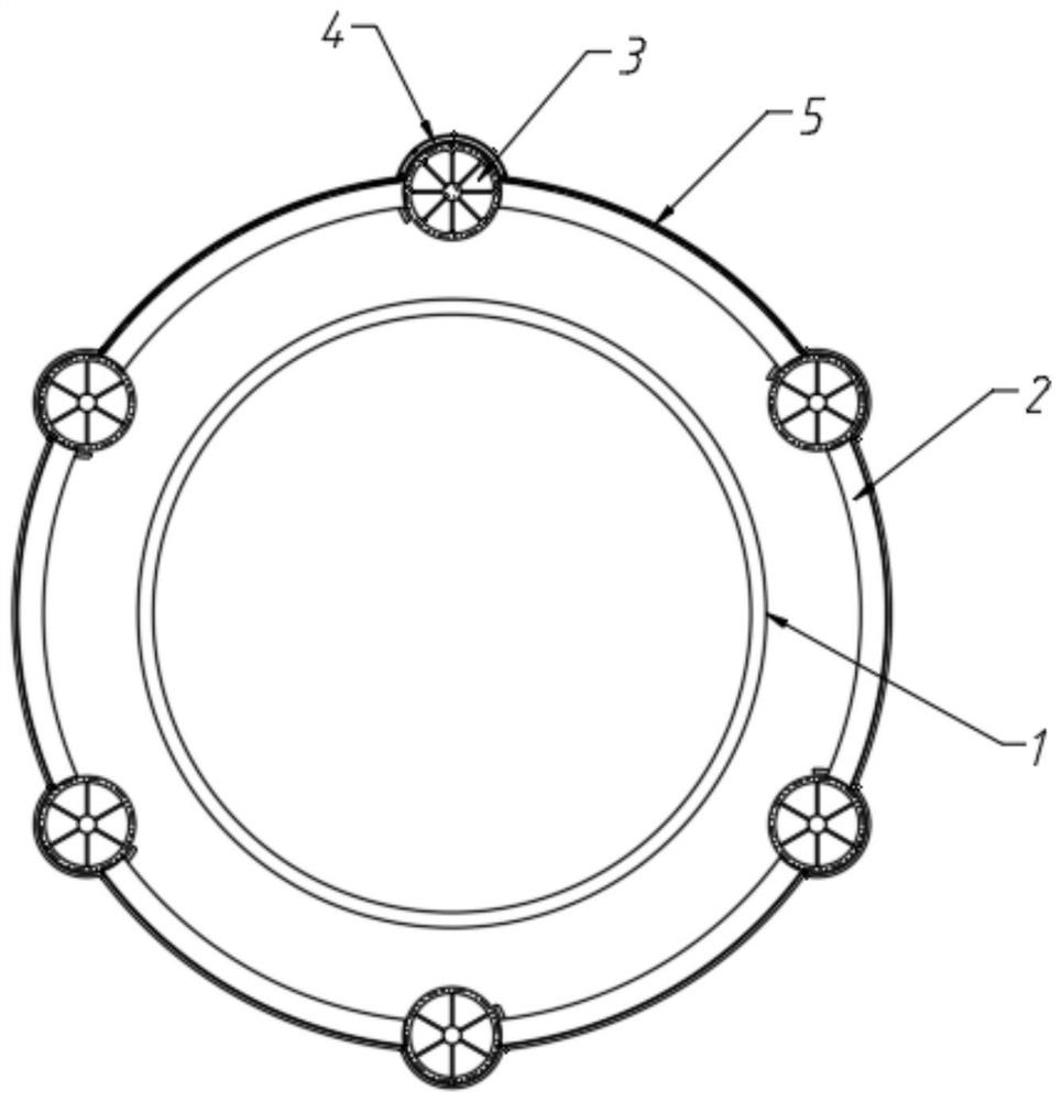
[0025] refer to Figure 1-5 , a fast heat dissipation enclosure for outdoor lasers, including:

[0026] The first housing 1, the interior of which is used to install laser components;

[0027] The second shell 2, the second shell 2 is fixedly arranged on the outside of the first shell 1, that is, the first shell 1 is inside the second shell 2, and the second shell 2 is provided with a plurality of rotating ports parallel to its axis;

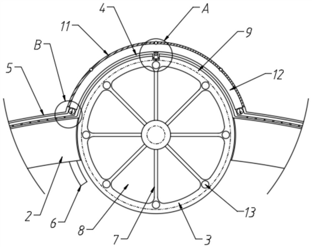
[0028] The rotating part is used to absorb heat and generate rotation. The rotating part includes a first magnet 6, a rotating cylinder 3 and a plurality of partition plates 7. The rotating cylinder 3 is arranged in the rotating port through the rotation of the rotating shaft, and the separating plates 7 are arranged on the rotating cylinder 3. Inside, the length and width respectively extend axially and radially along the rotating cylinder 3. The interior of the rotating cylinder 3 is divided into a plurality of fan-shaped and mutually indepen...

Embodiment 2

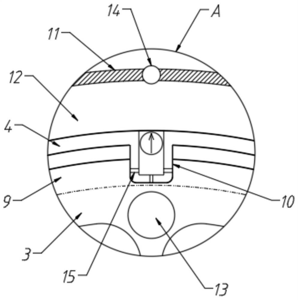
[0037] The difference between this embodiment and the first embodiment is that the elastic sheet 11 is made of rubber material, and the third magnet 14 is arranged on the elastic sheet 11, and a plurality of second magnets 13 are embedded in the wall of the rotating cylinder 3. The second magnets 13 are equally spaced along the circumferential direction of the rotating cylinder 3, and the distribution of magnetic poles between two adjacent second magnets 13 is opposite; specifically, during the rotation of the rotating cylinder 3, the third magnet 14 frame is subject to attraction and repulsion Force, and then cause the elastic sheet 11 to produce periodic fluctuations, and finally cause the gas flow in the suction chamber 12; compared with Embodiment 1, this solution can make the elastic sheet 11 produce stable vibration when the laser is running.


PUM


Abstract

The invention discloses a rapid heat dissipation shell for an outdoor laser. The shell comprises a first shell internally used for installing a laser element, a second shell and a rotating part, wherein the second shell is fixedly arranged on the outer side of the first shell, which means that the first shell is located in the second shell, and a plurality of rotating openings parallel to the axis of the second shell are formed in the second shell; the rotating part is used for absorbing heat and generating rotation, the rotating part comprises a first magnet, a rotating cylinder and a plurality of partition plates, the rotating cylinder is rotatably arranged in the rotating openings through a rotating shaft, the partition plates are arranged in the rotating cylinder, and the length and the width of the partition plates extend in the axial direction and the radial direction of the rotating cylinder correspondingly; and the interior of the rotating cylinder is divided into a plurality of sector-shaped containing cavities through the partition plates, wherein the containing cavities are independent of one another and do not connect with one another. By arranging the rotating part, the rotating part can continuously rotate after absorbing heat, and in the rotating process of the rotating cylinder, a high-temperature magnetic fluid in the rotating cylinder is continuously rotated to the outside for heat dissipation so that the heat dissipation rate of the shell is increased.

Description

technical field [0001] The invention belongs to the technical field of lasers, in particular to a fast heat dissipation shell for an outdoor laser. Background technique [0002] For lasers, the working temperature of each component is very important. In order for the laser to work normally, the temperature of the internal components of the laser must be strictly controlled within a certain range, otherwise, these components will not work normally, and the required laser cannot be obtained. . However, heat sources such as laser pump sources and laser crystals will generate a lot of heat during operation. Therefore, with the operation of the laser, the temperature of these optical components will continue to rise. If the temperature of these components cannot be effectively reduced, then Lasers will not work. Therefore, the cooling system of the laser is very important. [0003] At the same time, for lasers used outdoors, because the dust and impurities outdoors are more se...

Claims


Application Information

Patent Timeline
Patent Type & Authority Applications(China)
IPC IPC(8): H01S3/02H01S3/04
CPCH01S3/02H01S3/0405
Inventor 伍章明
Owner 伍章明
Why Eureka
Try Eureka