
A Relativistic Magnetron with Double-terminal Emitting Cathode Structure

A relativistic magnetron and emission cathode technology, which is applied in the microwave field, can solve the problems of device efficiency reduction, electronic energy loss, etc., and achieve the effect of improving output power and power conversion efficiency and being easy to implement

Active Publication Date: 2022-05-03
UNIV OF ELECTRONICS SCI & TECH OF CHINA
View PDF9 Cites 0 Cited by
  • Summary
  • Abstract
  • Description
  • Claims
  • Application Information

AI Technical Summary

Problems solved by technology

However, experiments have shown that the electron passing rate of the anode foil is usually not more than 70%, and the electrons that fail to pass through the anode foil will not enter the high-frequency structure to participate in the injection wave interaction, so the introduction of the anode foil will cause the loss of electron energy. Device efficiency decreases

Method used


Image

  • A Relativistic Magnetron with Double-terminal Emitting Cathode Structure
  • A Relativistic Magnetron with Double-terminal Emitting Cathode Structure
  • A Relativistic Magnetron with Double-terminal Emitting Cathode Structure

Examples


Embodiment Construction

[0027] In order to better illustrate the purpose, advantages and technical ideas of the present invention, the present invention will be further elaborated below in conjunction with specific embodiments. It should be noted that the specific examples given below are only for the purpose of explaining the present invention in detail, and do not limit the present invention.

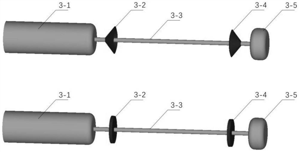
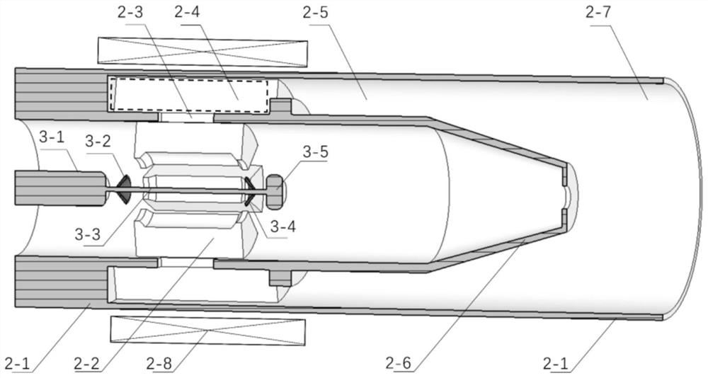
[0028] The cathode structure in this embodiment is as figure 2 As shown, it includes an upstream cathode end cap 3-1, an upstream cathode 3-2, a central connection conductor 3-3, a downstream cathode 3-4, and a downstream cathode end cap 3-5. In this embodiment, the upstream cathode 3-2, and The downstream cathode 3-4 adopts a hollow conical structure, the upstream cathode end cap 3-1 is cylindrical with rounded corners at the right end, and the downstream cathode end cap 3-5 is also cylindrical with rounded corners at both ends.

[0029] The upstream hollow conical cathode 3-2 has the same structure as th...


PUM

PropertyMeasurementUnit
radiusaaaaaaaaaa
lengthaaaaaaaaaa
radiusaaaaaaaaaa

Abstract

The invention discloses a relativistic magnetron with a double-terminal emitting cathode structure, which belongs to the field of microwave technology. The relativistic magnetron is a full-cavity axial extraction structure, including an anode shell, a high-frequency structure, an energy coupling slot, a fan-shaped waveguide, a coaxial waveguide, a TEM‑TM01 mode converter, an output circular waveguide, a guiding magnetic field coil, and a cathode structure , wherein the cathode structure includes two cathode end caps, two emitter cathodes arranged symmetrically, and a central connecting conductor. The invention adopts the virtual cathode scheme, which can effectively solve the problems of pulse shortening, frequency drift, and efficiency reduction caused by the plasma generated by explosive emission in the interaction interval, and can effectively improve the output power and power conversion of the relativistic magnetron efficiency.

Description

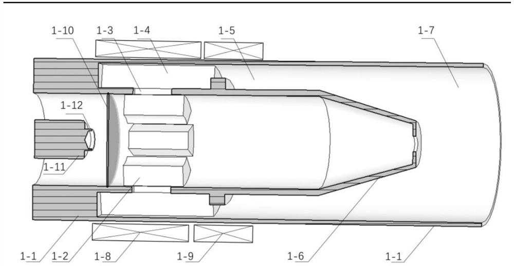
technical field [0001] The invention belongs to the field of microwave technology, and in particular relates to a cathode structure applied to a relativistic magnetron. Background technique [0002] Relativistic magnetrons are widely used in various high-power microwave systems due to their simple and compact structure and high conversion efficiency. However, high-power microwave devices have always had the problem of pulse shortening. Pulse shortening refers to the phenomenon that the output microwave pulse is terminated earlier than the electron beam pulse that generates the high power microwave. In response to the long pulse output requirements of high-power microwave sources, research on virtual cathode relativistic magnetrons is being vigorously carried out at home and abroad. [0003] An existing relativistic magnetron based on virtual cathode technology such as figure 1 Shown (An efficient all cavityaxial extractionrelativistic magnetron with virtual cathode[J],R.C...

Claims


Application Information

Patent Timeline
Patent Type & Authority Patents(China)
IPC IPC(8): H01J23/05H01J23/09H01J25/55
CPCH01J23/05H01J23/09H01J25/55H01J2225/55H01J2223/05H01J2223/09
Inventor 程仁杰李天明汪海洋胡标李浩周翼鸿
Owner UNIV OF ELECTRONICS SCI & TECH OF CHINA
Learn More