Automatic drainer shell structure
A technology of automatic drainage and shell structure, applied in the direction of non-rotational vibration suppression, steam traps, mechanical equipment, etc., can solve the problem of not being able to check the water accumulation inside the lower cover, so as to facilitate timely maintenance, ensure the safety of use, and structure simple effect
- Summary
- Abstract
- Description
- Claims
- Application Information
AI Technical Summary
Problems solved by technology
Method used
Image
Examples
Embodiment 1
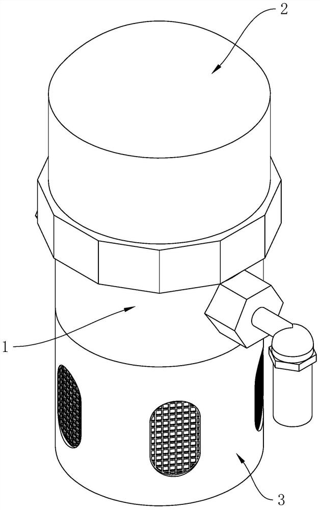
[0042] The embodiment of the present application discloses a housing structure of an automatic drainer. refer to figure 1, the shell structure includes a drainer body 1, an upper cover 2 and a lower cover 3, the lower end of the upper cover 2 is open, and the upper cover 2 is sealed with the upper end of the drainer body 1, and the lower cover 3 is connected with the drainer body 1 Lower end seal connection.
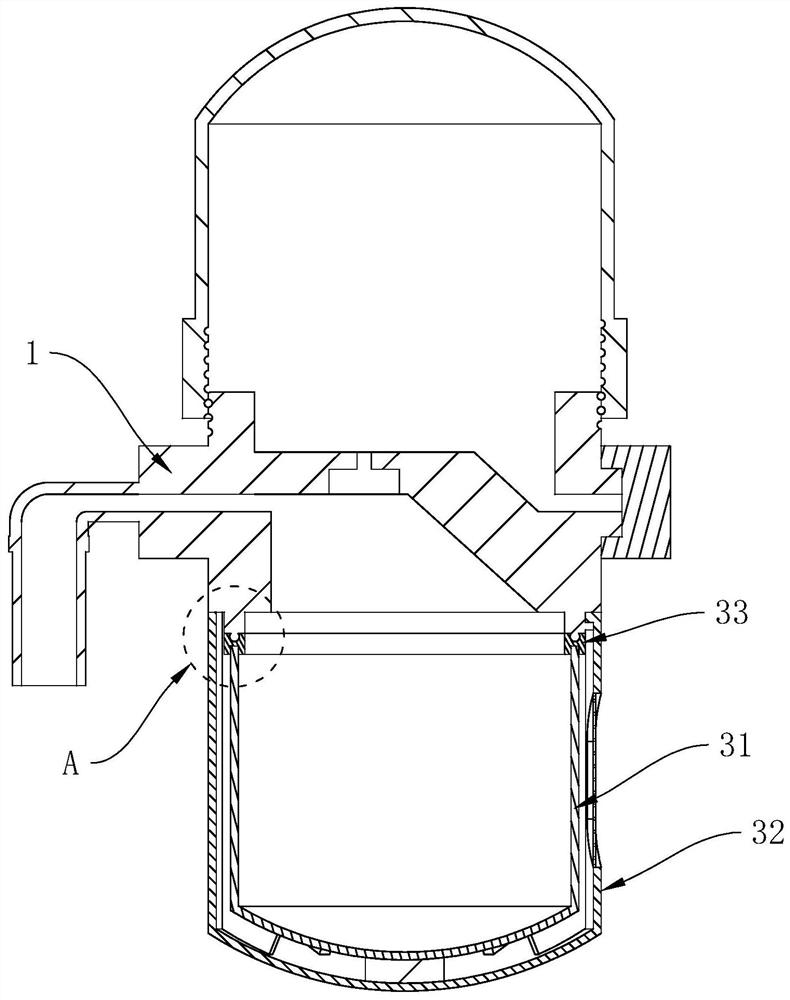
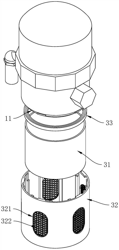
[0043] refer to figure 2 and image 3 , the lower cover 3 includes a transparent cover 31, a protective cover 32 and a rubber sealing ring 33, a joint 11 is arranged on the lower surface of the drainer body 1, the sealing ring is arranged between the transparent cover 31 and the joint 11, and the protective cover 32 covers the transparent The cover 31 is also connected to the joint 11 ; wherein, the protective cover 32 is provided with a plurality of viewing slots 321 that pass through, and each viewing slot 321 is arranged equidistantly around the axis of the protec...
Embodiment 2
[0054] refer to Figure 7 The difference between this embodiment and Embodiment 1 is that no rubber buffer pad 326 and isolation protrusion 324 are provided inside the protective cover 32, and several rubber isolation strips 34 are arranged inside the protective cover 32, each The rubber spacer strips 34 are arranged circumferentially around the axis of the protective cover 32, and the lower ends of each rubber spacer strip 34 extend into the bottom of the protective cover 32, so that the lower ends of each rubber spacer strip 34 can face the protective cover 32. The axis direction bending setting.
[0055] Wherein, a plurality of connecting grooves 327 are arranged on the inner wall of the protective cover 32, and each connecting groove 327 is arranged equidistantly around the axis of the protective cover 32. Connecting bars embedded in the connecting groove 327 are arranged on one side of the joint.
[0056] Compared with Embodiment 1, when the transparent cover 31 is inst...
Embodiment 3
[0058] refer to Figure 8 and Figure 9 The difference between this embodiment and Embodiment 1 is that the protective cover 32 includes several arc-shaped metal sheets 35, the upper ends of each arc-shaped metal sheet 35 are connected to the outer wall of the joint 11 in rotation, and each arc-shaped metal sheet The axis of the rotating shaft between the piece 35 and the joint 11 is arranged perpendicular to the axis of the joint 11 , and each arc-shaped metal piece 35 is detachably connected to the end away from the joint 11 .
[0059] refer to Figure 9 and Figure 10 , on the side of each arc-shaped metal sheet 35 away from the axis of the joint 11, a limit rod 351 is arranged, each limit rod 351 is arranged on the end of the arc-shaped metal sheet 35 away from the joint 11, and each limit The cross-sections of the rods 351 are arranged in a fan shape. When the arc-shaped metal sheets 35 are gathered together to form a complete protective cover 32, each limiting rod 351...
PUM
 Abstract
Description
Claims
Application Information
 - R&D Engineer
- R&D Manager
- IP Professional
- Industry Leading Data Capabilities
- Powerful AI technology
- Patent DNA Extraction
Browse by: Latest US Patents, China's latest patents, Technical Efficacy Thesaurus, Application Domain, Technology Topic, Popular Technical Reports.
© 2024 PatSnap. All rights reserved.Legal|Privacy policy|Modern Slavery Act Transparency Statement|Sitemap|About US| Contact US: help@patsnap.com


