
Wind speed monitoring device for air inlet shaft in mine ventilation system

A technology of mine ventilation system and monitoring device, which is applied to mine/tunnel ventilation, mining equipment, earth-moving drilling, etc., can solve the problems of monitoring result error, large difference in tunnel wind speed, large difference in tunnel structure, etc. Air quality, damage avoidance, error reduction effect

Active Publication Date: 2021-06-01
辽阳县寒岭正皓矿业有限公司
View PDF5 Cites 0 Cited by
  • Summary
  • Abstract
  • Description
  • Claims
  • Application Information

AI Technical Summary

Problems solved by technology

[0003] Due to the large difference in the internal structure of the tunnel, the airflow usually has different wind speeds along the inner wall of the tunnel and the center of the tunnel, and the local resistance loss cannot be defined. Therefore, the wind speeds in various places inside the tunnel vary greatly. The existing monitoring devices are usually fixedly installed in A certain position of the air inlet shaft can only monitor the wind speed at a local position, and there are errors in the monitoring results. Therefore, those skilled in the art provide a wind speed monitoring device for the air inlet shaft in the mine ventilation system to solve the problem of the above-mentioned background technology. proposed question

Method used


Image

  • Wind speed monitoring device for air inlet shaft in mine ventilation system
  • Wind speed monitoring device for air inlet shaft in mine ventilation system
  • Wind speed monitoring device for air inlet shaft in mine ventilation system

Examples


Embodiment Construction

[0020] The following will clearly and completely describe the technical solutions in the embodiments of the present invention with reference to the accompanying drawings in the embodiments of the present invention. Obviously, the described embodiments are only some, not all, embodiments of the present invention. Based on the embodiments of the present invention, all other embodiments obtained by persons of ordinary skill in the art without making creative efforts belong to the protection scope of the present invention.

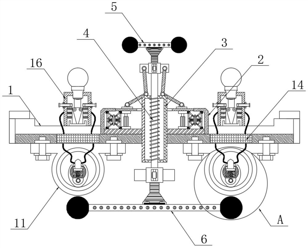
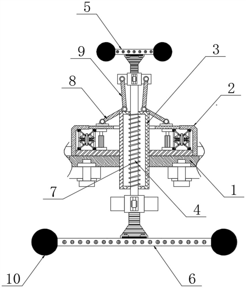
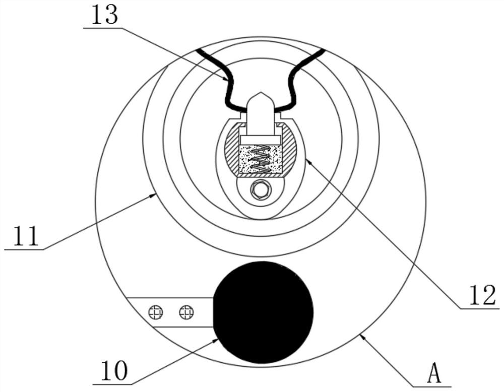
[0021] see Figure 1-5 , a wind speed monitoring device entering an air shaft in a mine ventilation system, comprising a fixed frame 1, the inside of the fixed frame 1 is fixedly connected with a limit frame 2, the inside of the limit frame 2 is fixedly connected with a protective frame 3, and the inside of the protective frame 3 The arc is embedded with the rotating rod 4, the top of the rotating rod 4 is fixedly connected with the outer wind direction rod 5,...


PUM


Abstract

The invention relates to the technical field of mine ventilation detection, and particularly relates to a wind speed monitoring device for an air inlet shaft in a mine ventilation system. A limiting frame is fixedly connected to the interior of a fixing frame; a protective frame is fixedly connected to the interior of the limiting frame; a rotating rod is connected to the interior of the protective frame in an embedded mode with an radian; an outer wind direction rod is fixedly connected to the top end of the rotating rod; an inner wind direction rod is fixedly connected to the bottom end of the rotating rod; a first connecting rod is movably connected to the top end of the outer surface of the limiting frame; a second connecting rod is movably connected to the top end of the first connecting rod; and glass covers are fixedly connected to the positions, located on the two sides of the inner wind direction rod, of the bottom end of the fixing frame. When the monitoring process in unit time is carried out, the positions of the first connecting rod and the second connecting rod are limited to be static, the rotating condition of the outer wind direction rod is observed when the inner wind direction rod is located at different depths in the air inlet shaft, and therefore the error of wind speed monitoring data in the air inlet shaft is reduced.

Description

technical field [0001] The invention relates to the technical field of mine ventilation detection, in particular to a wind speed monitoring device for an air inlet shaft in a mine ventilation system. Background technique [0002] The mine ventilation system is composed of two parts: the fan and the ventilation network. After entering the mine from the air inlet shaft, the air flow passes through various wind sites in the mine, and then enters the return air shaft, and is discharged from the mine by the return air shaft. The basic task of the mine ventilation system is :Supply enough fresh air underground to meet the needs of personnel for oxygen; dilute toxic and harmful gases and dust underground to ensure safe production; adjust underground climate to create a good working environment. [0003] Due to the large difference in the internal structure of the tunnel, the airflow usually has different wind speeds along the inner wall of the tunnel and the center of the tunnel, a...

Claims


Application Information

Patent Timeline
Patent Type & Authority Applications(China)
IPC IPC(8): E21F1/00
CPCE21F1/00
Inventor 韩珂成
Owner 辽阳县寒岭正皓矿业有限公司
Learn More