Intelligent textile equipment
A kind of textile equipment and intelligent technology, applied in the field of intelligent manufacturing equipment, can solve the problems of unclean wire body and winding coil, and achieve the effect of reducing knotting phenomenon, reducing workload and improving safety.
- Summary
- Abstract
- Description
- Claims
- Application Information
AI Technical Summary
Problems solved by technology
Method used
Image
Examples
Embodiment 1
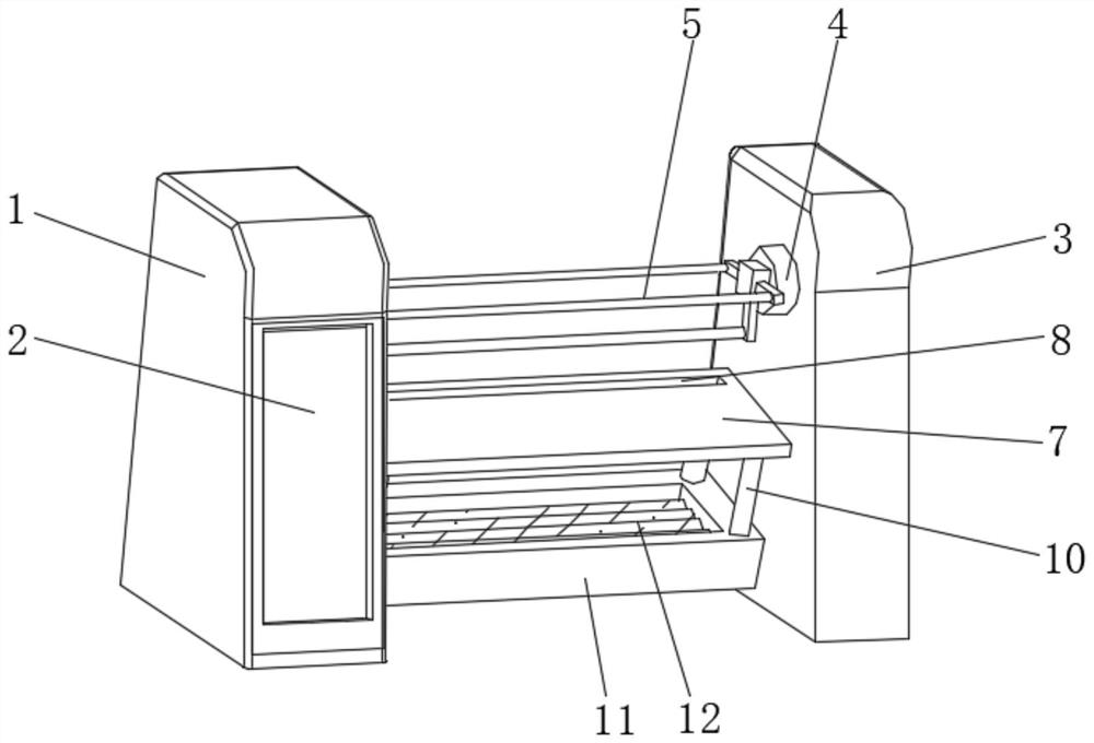
[0030] see figure 1 , the present invention provides a technical solution: a kind of intelligent textile equipment, including a workbench 1 and a connection platform 3, an operation display screen 2 is fixedly installed in front of the workbench 1, and a left side of the outer surface of the connection platform 3 is fixedly connected with Fixed seat 4, the outer surface of fixed seat 4 is connected with rotating bearing in rotation, the outer surface of rotating bearing is evenly fixedly connected with first winding shaft 5, and the first winding shaft 5 is provided with three, and the outer surface of first winding shaft 5 is sheathed There is a fixing mechanism 6, and the left ends of the three first winding shafts 5 are rotationally connected with the right side of the workbench 1 through the rotating disk, and the right side of the workbench 1 is fixedly connected with a side plate 7 below the rotating disk, and the side plate 7 The top is provided with a strip groove 8, t...
Embodiment 2
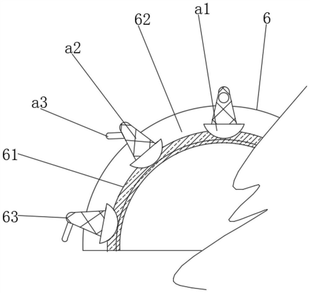
[0032] see figure 2The present invention provides a technical solution: the fixing mechanism 6 includes a fixed casing 61, the inner surface of the fixed casing 61 is fixedly connected with the outer surface of the first winding shaft 5, and the outer surface of the fixed casing 61 is provided with a chute 62, A fixing assembly 63 is slidably connected to the outer surface of the chute 62 .
[0033] The fixed assembly 63 includes a sliding base a1, the bottom of the sliding base a1 is slidably connected with the inner surface of the chute 62, the top of the sliding base a1 is fixedly connected with a tapered post a2, and the top of the tapered post a2 is rotatably connected with a baffle a3.
Embodiment 3
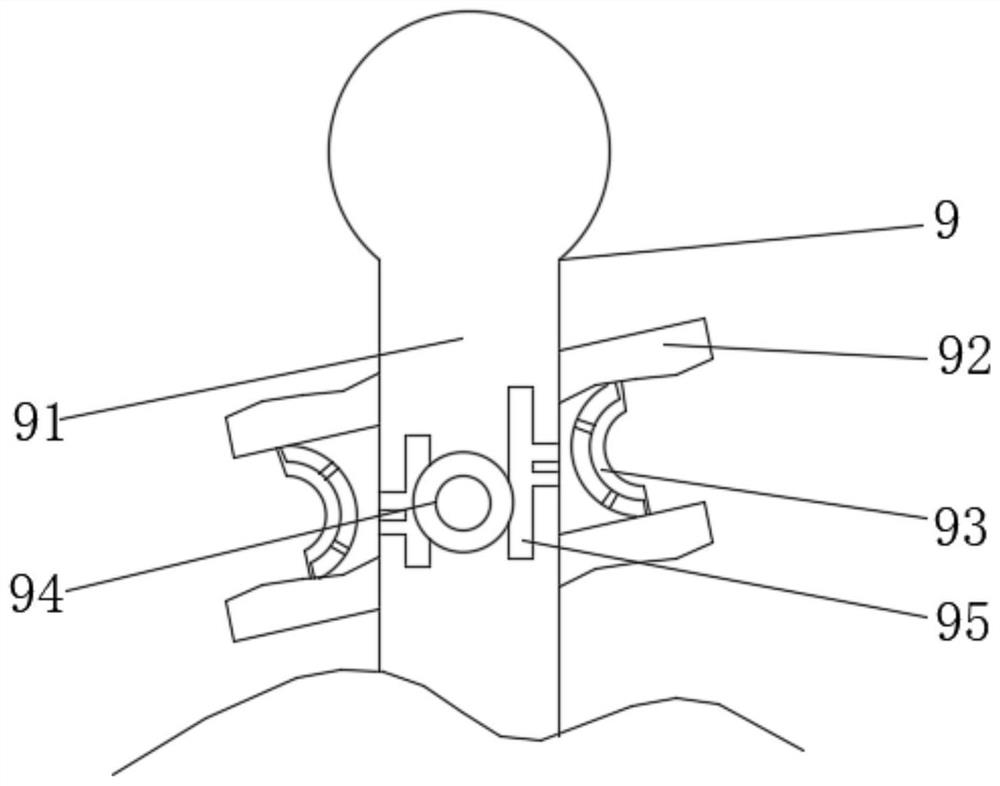
[0035] see image 3 , the present invention provides a kind of technical scheme: combing mechanism 9 comprises combing rod 91, and the left and right ends of combing rod 91 are respectively movable connected with the left and right sides of the inner surface of strip groove 8, and the outer surface of combing rod 91 is evenly fixedly connected with combing rod 91. Teeth 92, a piston rod 93 is fixedly connected between the opposite sides of the two combing teeth 92, the outer surface of the combing rod 91 is connected with a hydraulic bag 94, and the bottom of the hydraulic bag 94 is provided with a through groove on the inner surface of the combing rod 91 95. The liquid enters the inside of the through groove 95 and pushes the piston rod 93 forward, and the textile thread between the comb teeth 92 is pushed outwards, so as to avoid unnecessary thread ends being stuck between the comb teeth 92 when combing.
PUM
 Abstract
Description
Claims
Application Information
 - R&D
- Intellectual Property
- Life Sciences
- Materials
- Tech Scout
- Unparalleled Data Quality
- Higher Quality Content
- 60% Fewer Hallucinations
Browse by: Latest US Patents, China's latest patents, Technical Efficacy Thesaurus, Application Domain, Technology Topic, Popular Technical Reports.
© 2025 PatSnap. All rights reserved.Legal|Privacy policy|Modern Slavery Act Transparency Statement|Sitemap|About US| Contact US: help@patsnap.com


