Vertical anaerobic fermentation tank

An anaerobic fermentation tank, vertical technology, applied in the field of vertical anaerobic fermentation tanks, can solve the problems of heavy weight of mixing, inability to mix repeatedly, different materials, etc., and achieve the effect of reducing the rotational force

Inactive Publication Date: 2021-06-01
李志杰
View PDF0 Cites 0 Cited by
  • Summary
  • Abstract
  • Description
  • Claims
  • Application Information

AI Technical Summary

Problems solved by technology

[0003] Aiming at the deficiencies of the prior art, the present invention provides a vertical anaerobic fermentation tank, which solves the problem that the air pressure environment inside the tank will be separated from the outside air due to the fermentation of the anaerobic fermentation tank. The air is different, and because there is no air circulation inside the tank, the substances inside the tank cannot be mixed repeatedly. In order to solve this kind of problem, a stirrer is usually installed inside the tank, or the tube is directly assembled to the rotating frame The material inside the pipe body is stirred and mixed by rotating, but during assembly and mixing, due to the heavy weight of the tank body mixed with the internal wastewater, the rotation speed will be increased due to inertia during rotation, resulting in the inside of the tank body. Wastewater will be squeezed to one side due to the centrifugal force generated by the rotation, but still cannot be fully mixed.

Method used


Image

  • Vertical anaerobic fermentation tank
  • Vertical anaerobic fermentation tank
  • Vertical anaerobic fermentation tank

Examples


Embodiment 1

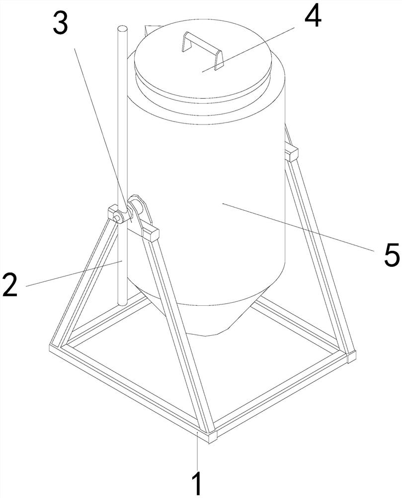
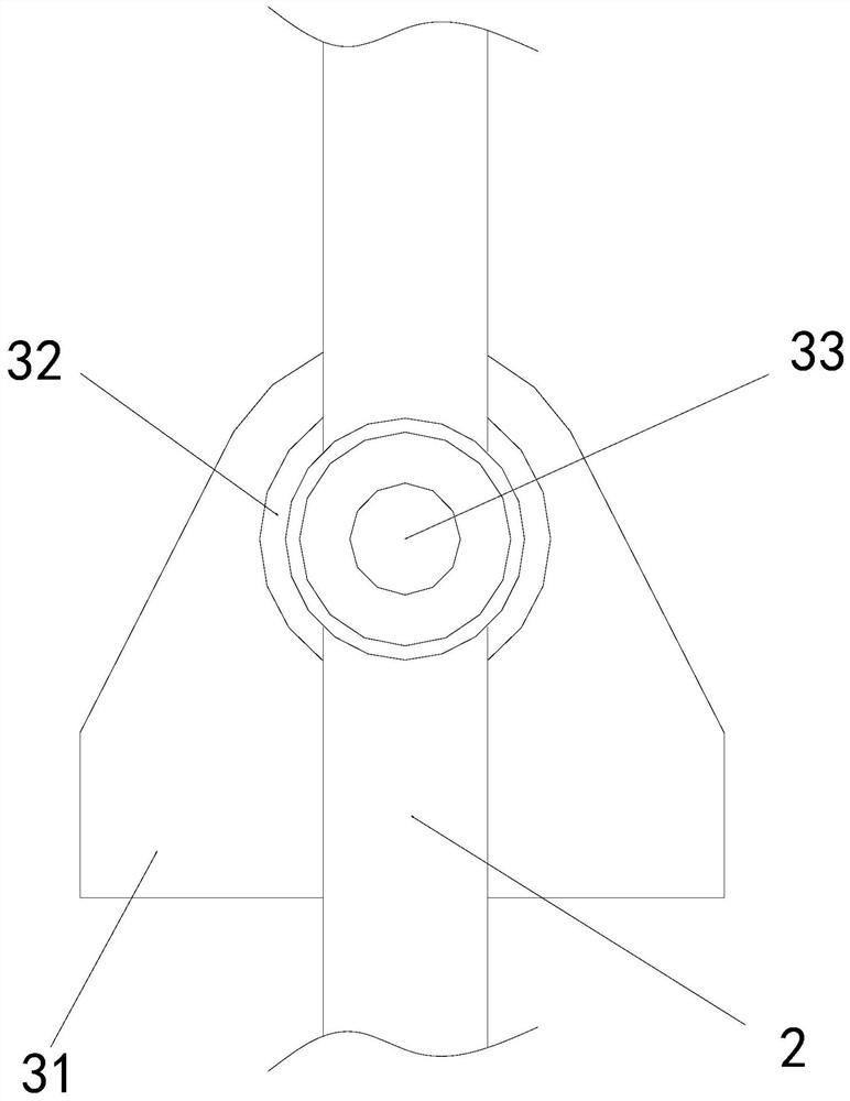
[0025] as attached figure 1 To attach Figure 4 As shown, the present invention provides a vertical anaerobic fermentation tank, the structure of which includes a support frame 1, a balance bar 2, a rotating mechanism 3, an end cover 4, and a tank body 5. The outer wall of the middle section of the balance bar 2 is nested and engaged with the The inner wall of the front end of the rotating mechanism 3, the inner lower end of the rotating mechanism 3 is fixed to the inner wall of the upper end of the support frame 1 by screws, the lower end of the end cover 4 is fixed to the upper end of the tank body 5 through buckles, and the front and rear ends of the tank body 5 are movably engaged Between the rotating mechanisms 3, there are two rotating mechanisms 3, which are relatively arranged on the outer walls of both ends of the tank body 5. After the rotating mechanisms 3 set up at both ends are assembled with the tank body 5, the two ends of the tank body 5 When rotating, the rot...

Embodiment 2

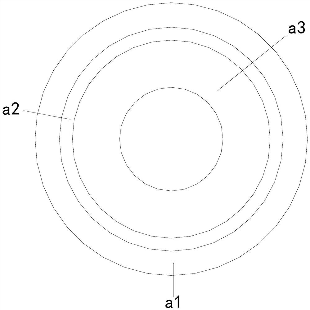
[0032] as attached Figure 4 As shown: the speed reducer a3 is composed of a friction device b1, a guide ring b2, a reducer b3, an embedded ring b4, and a ring body b5. One end of the friction device b1 is welded to the outer wall of the embedded ring b4, and the guide ring The outer wall of the ring b2 is nested and fitted on the inner wall of the friction device b1, the outer wall of one end of the reducer b3 is embedded and fixed inside the ring body b5, the outer wall of the embedded ring b4 is nested and fitted on the inner wall of the ring body b5, and the outer wall of the ring body b5 is embedded Fastened to the inner wall of the limit ring a2, there are three speed reducers b3, which are arranged circularly inside the ring body b5. The rotation speed when rotating is slowed down to a certain extent.

[0033] as attached Figure 5 To attach Figure 7 As shown: the friction device b1 is composed of an inlay device d1, a positioning ring d2, and an assembly seat d3. T...


PUM


Abstract

The invention provides a vertical anaerobic fermentation tank which structurally comprises a supporting frame, a balance rod, a rotating mechanism, an end cover and a tank body. The outer wall of the middle section of the balance rod is nested and clamped to the inner wall of the front end of the rotating mechanism, the lower end of the interior of the rotating mechanism is fixed to the inner wall of the upper end of the supporting frame through screws, and the front end and the rear end of the tank body are movably clamped between the two ends of the rotating mechanism. During use, when waste water enters the equipment and the equipment is started to rotate, the rotation of the tank body enables the waste water in the tank body to be extruded to the two ends by centrifugal force generated by rotation and to be fully mixed, vibration generated when a friction device collides with a speed reducer through rotation can be conducted to the tank body, waste water filling the tank body is vibrated through self vibration of the tank body, part of rotating force of the equipment can be reduced through collision, the rotating force of the equipment is reduced, and the situation that waste water in the equipment is pressed to the two ends and cannot be movably mixed due to high-strength centrifugal force is avoided.

Description

technical field [0001] The invention relates to the field of anaerobic fermentation equipment, and more specifically relates to a vertical anaerobic fermentation tank. Background technique [0002] With the rapid development of industry, industrial production will inevitably produce some waste water, but this kind of waste water is very polluting to the environment and cannot be directly discharged into the environment. It is necessary to use special equipment to treat and degrade the waste water, so that the waste water meets the discharge requirements. standard, but the method used to treat wastewater is usually to use filtration or fermentation to treat wastewater, but when using fermentation, because the performance of anaerobic fermentation tanks is more stable, anaerobic fermentation tanks are usually used to treat wastewater Part of the industrial wastewater is treated, because the anaerobic fermentation tank cuts off the contact between the inside of the tube and the...

Claims


Application Information

Patent Timeline
Patent Type & Authority Applications(China)
IPC IPC(8): C02F3/28B01F11/00
CPCC02F3/2866B01F31/50B01F2101/305
Inventor 李志杰
Owner 李志杰
Why Eureka
Try Eureka