
Hoisting device capable of avoiding stall in hoisting process by utilizing centrifugal force effect

A lifting device and centrifugal force technology, applied in safety devices, transportation and packaging, load hanging components, etc., can solve problems such as heavy weight, mechanical fatigue of lifting devices, and impact on the life safety of surrounding workers, and reduce response delays. , Improve the overall response speed and avoid the effect of response delay

Inactive Publication Date: 2021-06-01
陈安玲
View PDF0 Cites 2 Cited by
  • Summary
  • Abstract
  • Description
  • Claims
  • Application Information

AI Technical Summary

Problems solved by technology

[0005] Aiming at the deficiencies of the prior art, the present invention provides a hoisting device that utilizes centrifugal force to avoid stalling during the hoisting process. It has the advantages of preventing the slippage of the pay-off shaft of the hoisting device on the railway track and avoiding the fall of the rails to injure people. It solves the problem of During the lifting process of the steel rail, because the integrity of the steel rail is relatively strong and its weight is relatively large, during the lifting work, it may cause mechanical fatigue of the lifting device, resulting in the discharge shaft of the lifting device Slipping occurs, causing the rail to drop rapidly at a high place, and the falling rail will have a serious impact on the safety of the surrounding staff

Method used


Image

  • Hoisting device capable of avoiding stall in hoisting process by utilizing centrifugal force effect
  • Hoisting device capable of avoiding stall in hoisting process by utilizing centrifugal force effect
  • Hoisting device capable of avoiding stall in hoisting process by utilizing centrifugal force effect

Examples


Embodiment Construction

[0024] The following will clearly and completely describe the technical solutions in the embodiments of the present invention with reference to the accompanying drawings in the embodiments of the present invention. Obviously, the described embodiments are only some, not all, embodiments of the present invention. Based on the embodiments of the present invention, all other embodiments obtained by persons of ordinary skill in the art without making creative efforts belong to the protection scope of the present invention.

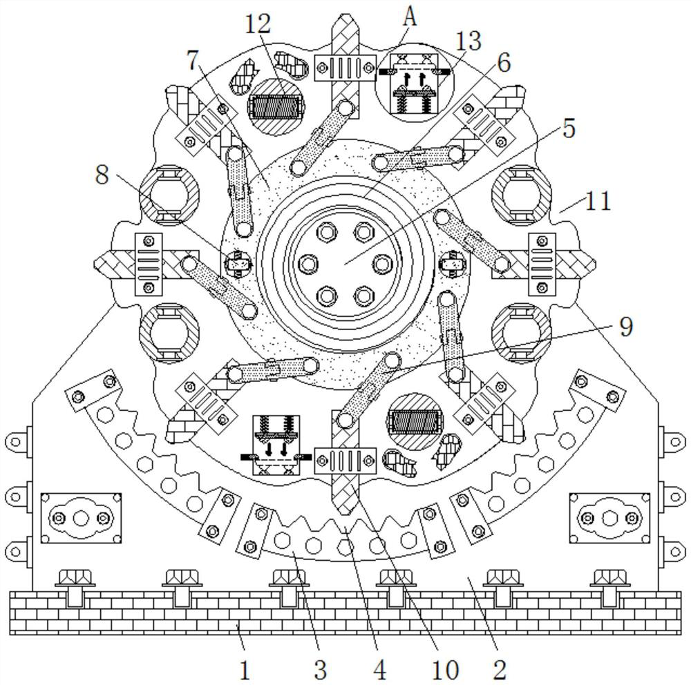
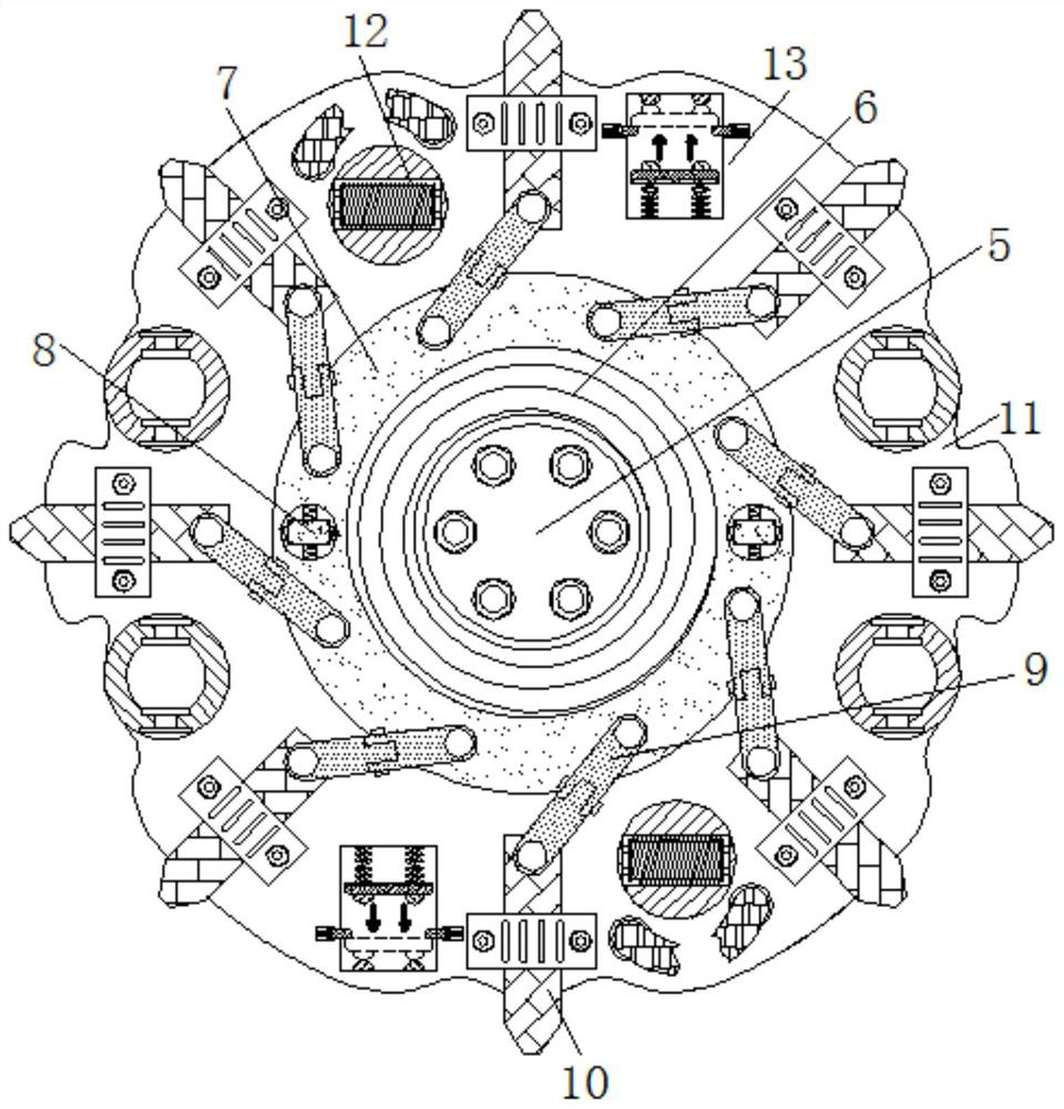
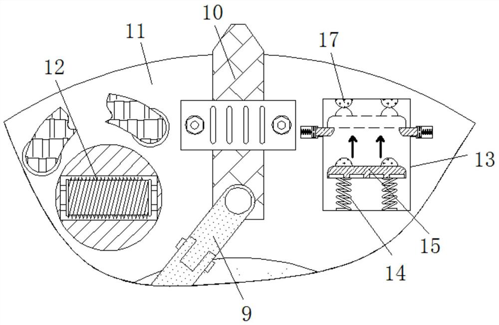
[0025] see Figure 1-5 , a hoisting device that utilizes centrifugal force to avoid stalling in the hoisting process, comprising a mounting base 1, a fixing plate 2 is fixedly connected to the top of the mounting base 1, an arc-shaped block 3 is fixedly connected to the front of the fixing plate 2, and the arc-shaped block The number of 3 is not less than three, and the centers of circles of these arc-shaped blocks 3 are the axes of the drive shaft 5, the top ...


PUM


Abstract

The invention relates to the technical field of railway components, and discloses a hoisting device capable of avoiding stall in the hoisting process by utilizing a centrifugal force effect. The hoisting device comprises a mounting base, the top of the mounting base is fixedly connected with a fixing plate, the front face of the fixing plate is fixedly connected with an arc-shaped block, the top of the arc-shaped block is provided with a limiting groove, and a driving shaft is movably connected to the interior of the fixed plate. According to the hoisting device capable of avoiding stall in the hoisting process under the centrifugal force effect, when the stall situation occurs, a fixed contact makes contact with a movable contact under the centrifugal force effect at the moment, the driving shaft is further made to stop rotating, and therefore the effects that a pay-off shaft of the railway track hoisting device is prevented from slipping, and a steel rail is prevented from falling to hurt people are achieved. The movable contact and the fixed contact are electrically connected with an electromagnetic device so that the overall reaction speed of the device can be increased, the reaction delay of the hoisting device is reduced, and the effect of effectively avoiding the influence of the reaction delay on the reliability of the device is achieved.

Description

technical field [0001] The invention relates to the technical field of railway components, in particular to a hoisting device which utilizes centrifugal force to avoid stalling during hoisting. Background technique [0002] In the context of the rapid development of railways, the railway component industry has also maintained a relatively high level of development. The localization of equipment is one of the trends in railway components. Railway components have high strength, good toughness, excellent fatigue resistance and wear resistance, etc. One of its components, the rail, must have sufficient strength to ensure that the train runs safely, smoothly and uninterruptedly at the specified maximum speed. [0003] During the lifting process of the steel rail, because the integrity of the steel rail is relatively strong and its weight is relatively large, during the lifting work, it may cause mechanical fatigue of the lifting device, resulting in the discharge shaft of the lif...

Claims


Application Information

Patent Timeline
Patent Type & Authority Applications(China)
IPC IPC(8): B66C15/00B66C13/00
CPCB66C13/00B66C15/00
Inventor 陈安玲
Owner 陈安玲
Learn More