
Sectional material scribing device and method for saw cutting center modification and saw cutting center modification method

A profile and sawing technology, applied in laser welding equipment, welding equipment, metal processing equipment, etc., can solve the problems of high cost, inability to have engraving and cutting at the same time, and not suitable for popularization and application, so as to save space and ensure beautiful appearance sexual effect

Active Publication Date: 2021-06-01
济南天辰智能装备股份有限公司
View PDF5 Cites 0 Cited by
  • Summary
  • Abstract
  • Description
  • Claims
  • Application Information

AI Technical Summary

Problems solved by technology

However, the existing sawing center only has the function of profile cutting, and cannot have both functions of engraving and cutting at the same time. This requires a special engraving device to engrave the profile first, and then cut through the sawing center
However, the cost of the existing marking equipment is relatively high, and it is not suitable for popularization and application.

Method used


Image

  • Sectional material scribing device and method for saw cutting center modification and saw cutting center modification method
  • Sectional material scribing device and method for saw cutting center modification and saw cutting center modification method
  • Sectional material scribing device and method for saw cutting center modification and saw cutting center modification method

Examples


Embodiment 1

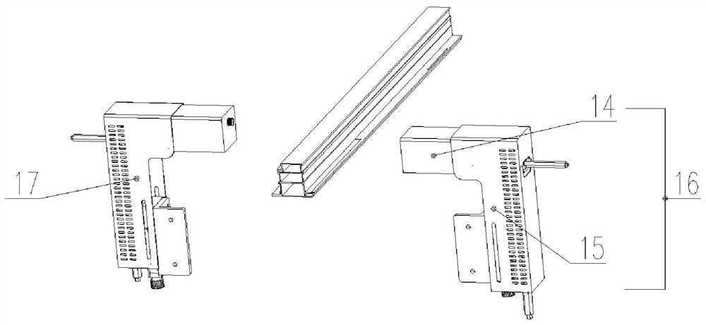
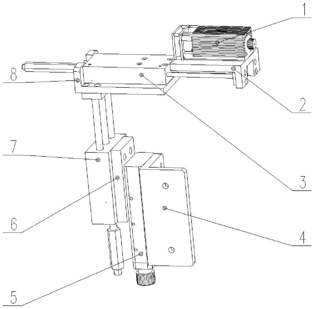
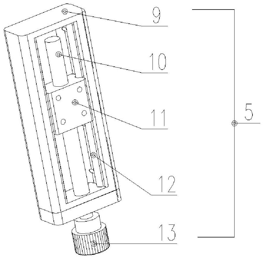
[0029] Such as Figure 1-3 As shown, the present invention is a first embodiment of a profile scoring device for refitting sawing centers, including a symmetrically arranged front scoring assembly 17 and a rear scoring assembly 16, the front scoring assembly 17 and the rear scoring assembly The scoring assembly 16 has the same structure; it also includes two fixed plates 4 and two vertical sliding mechanisms which are arranged symmetrically and have the same structure. Wherein, the fixing plate 4 is provided with a first installation part and a second installation part. Preferably, the shape of the fixing plate 4 is L-shaped, and the first installation part and the second installation part are respectively arranged on two planes perpendicular to each other. The fixed plate 4 is connected with the workbench at the front end of the sawing center feeding device through the first installation part, and a one-dimensional slide table 5 is installed on the second installation part o...

Embodiment 2

[0033] Such as Figure 4 As mentioned above, the second embodiment of the profile scoring device for refitting the sawing center of the present invention differs from the first embodiment in that, in this embodiment, only one fixing plate 4 and one vertical Straight slide mechanism, the vertical slide mechanism in the present embodiment comprises slide table connecting plate 18, and one side of described slide table connecting plate 18 is installed on the slider 11 of one-dimensional slide table 5, and described slide table connecting plate 18 The front and rear connecting frames 19 are installed on the other side of the front and rear connecting frames 19, and the horizontal connecting plates 8 of the front scoring line assembly 17 and the rear scoring line assembly 16 are all installed on the front and rear connecting frames 19.

[0034] Further, in this embodiment, the lower end of the lead screw 10 of the one-dimensional sliding table 5 is connected to the motor 20 through...


PUM


Abstract

The invention discloses a sectional material scribing device and method for saw cutting center modification and a saw cutting center modification method. The sectional material scribing device comprises fixing plates, a front scribing assembly and a rear scribing assembly, wherein the front scribing assembly and the rear scribing assembly are symmetrically arranged, and the fixing plates are installed on a workbench at the front end of a feeding device of a saw cutting center; each fixing plate is further provided with a one-dimensional sliding platform capable of vertically moving, and the one-dimensional sliding platform is provided with a vertical sliding mechanism; and the front scribing assembly and the rear scribing assembly each comprise a horizontal connecting plate, a second air cylinder is fixedly installed on each horizontal connecting plate, a laser is fixedly installed on the piston rod, moving horizontally, of each second air cylinder, and the lasers are driven by the vertical sliding mechanisms to move upwards and downwards along with the two horizontal connecting plates. According to the sectional material scribing device installed in front of the feeding device of the sawing center, the production application range of the sawing center can be broadened, and efficient, accurate and low-cost scribing treatment can be conducted on sectional materials.

Description

technical field [0001] The invention relates to the field of door frame processing, in particular to a profile marking device, a marking method and a sawing center modification method for refitting a sawing center. The straight material profile is equipped with a laser marking device according to the process requirements. Background technique [0002] During the processing of aluminum alloy doors and windows, for the frame material and mid-stiff material of the installation process, it is necessary to first engrave the installation position. However, the existing sawing center only has the function of profile cutting, and cannot have the functions of engraving and cutting at the same time. It is necessary to first engrave the profile through special engraving equipment, and then cut through the sawing center. However, the cost of the existing engraving equipment is relatively high, and it is not suitable for popularization and application. Contents of the invention [00...

Claims


Application Information

Patent Timeline
IPC IPC(8): B25H7/04B23K26/362
CPCB25H7/04B25H7/045B23K26/362Y02P70/10
Inventor 马益堂亓爱林赵殿蛟
Owner 济南天辰智能装备股份有限公司
Learn More